a
a
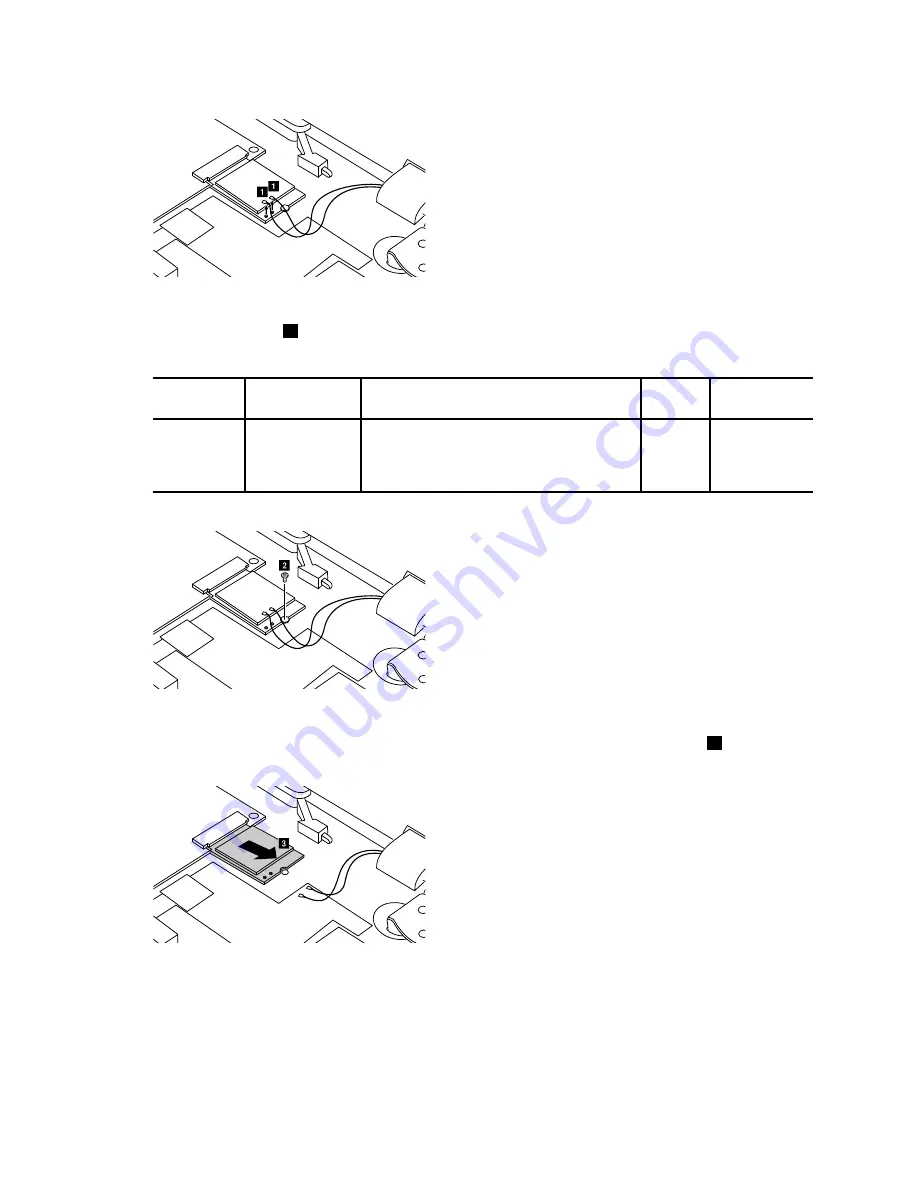
Figure 10. Disconnect antenna cables
Step 2.
Remove the screw
2
.
Table 5. Screw specifications — removing the WLAN & Bluetooth combo module
Screw
location
Number
Specifications
Color
Torque
WLAN&Bluetooth
combo card
to base
cover
1
M2 × 3mm, flat-head, nylon-coated
Black
1.85 +/-
0.15kgf-cm
b
Figure 11. Remove one screw
Step 3.
Pull out the WLAN & Bluetooth combo module in the direction shown by the arrow
3
.
c
Figure 12. Pull out the WLAN & Bluetooth combo module
Refer to Table 12 “Part numbers for FRUs (CRUs)” on page 43 to look up the Lenovo part numbers of
replacement WLAN & Bluetooth combo modules.
30
Hardware Maintenance Manual
Summary of Contents for N22-20
Page 1: ...Hardware Maintenance Manual Lenovo N22 20 Chromebook ...
Page 2: ......
Page 3: ...Hardware Maintenance Manual Lenovo N22 20 Chromebook ...
Page 4: ...First Edition February 2016 Copyright Lenovo 2016 ...
Page 6: ...iv Hardware Maintenance Manual ...
Page 11: ...DANGER DANGER DANGER DANGER Chapter 1 Safety information 5 ...
Page 12: ...6 Hardware Maintenance Manual ...
Page 13: ...PERIGO PERIGO PERIGO PERIGO Chapter 1 Safety information 7 ...
Page 14: ...PERIGO PERIGO PERIGO PERIGO DANGER DANGER 8 Hardware Maintenance Manual ...
Page 15: ...DANGER DANGER DANGER DANGER DANGER Chapter 1 Safety information 9 ...
Page 16: ...DANGER VORSICHT VORSICHT VORSICHT VORSICHT 10 Hardware Maintenance Manual ...
Page 17: ...VORSICHT VORSICHT VORSICHT VORSICHT Chapter 1 Safety information 11 ...
Page 18: ...12 Hardware Maintenance Manual ...
Page 19: ...Chapter 1 Safety information 13 ...
Page 20: ...14 Hardware Maintenance Manual ...
Page 21: ...Chapter 1 Safety information 15 ...
Page 22: ...16 Hardware Maintenance Manual ...
Page 23: ...Chapter 1 Safety information 17 ...
Page 24: ...18 Hardware Maintenance Manual ...
Page 46: ...40 Hardware Maintenance Manual ...
Page 48: ...42 Hardware Maintenance Manual ...
Page 54: ...48 Hardware Maintenance Manual ...
Page 56: ...50 Hardware Maintenance Manual ...
Page 58: ......
Page 59: ......
Page 60: ......


