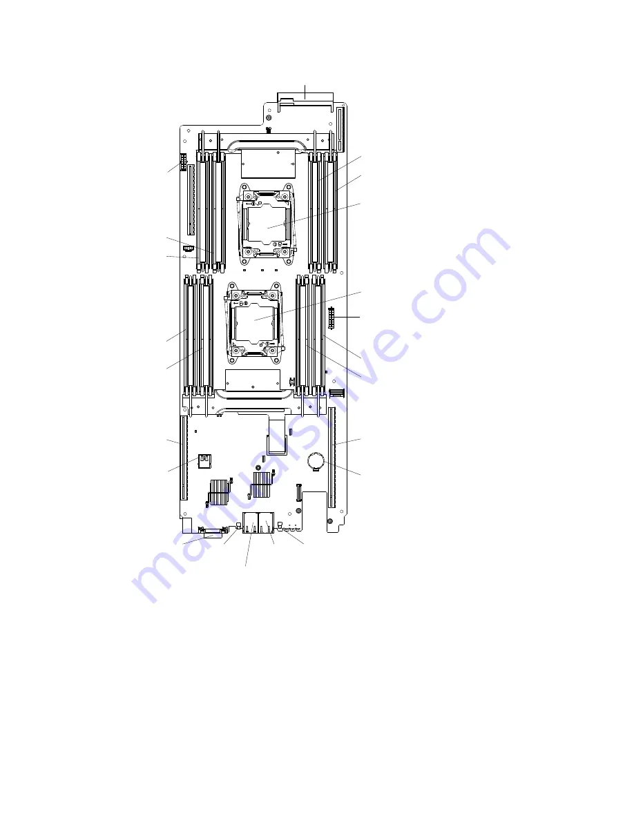
Power distribution
board connector
PCI riser
connector 1
Microprocessor 2
Microprocessor 1
Slot 6
Ethernet 1
connector
Ethernet 2
connector
KVM connector
NM1 switch
Power button
DIMM 16
DIMM 14
DIMM 11
DIMM 9
DIMM 6
DIMM 8
DIMM 3
DIMM 1
USB hypervisor key
Battery
Power connector
(Reserved for future use)
Power connector
(Reserved for future use)
Figure 10. Internal connectors on the system board
System-board switches and jumpers
The following illustration shows the location and description of the switches, jumpers, and buttons.
Important:
1. Before you change any switch settings or move any jumpers, turn off the server; then, disconnect all
power cords and external cables. Review the information in “Safety” on page v, “Installation guidelines”
on page 28, and “Turning off the server” on page 19.
2. Any system-board switch or jumper block that is not shown in the illustrations in this document are
reserved.
.
Components, features, and controls
25
Summary of Contents for NeXtScale n1200
Page 115: ...Chapter 6 Removing and replacing server components 101 ...
Page 117: ...Chapter 6 Removing and replacing server components 103 ...
Page 119: ...Chapter 6 Removing and replacing server components 105 ...
Page 135: ...Chapter 6 Removing and replacing server components 121 ...
Page 137: ...Chapter 6 Removing and replacing server components 123 ...
Page 139: ...Chapter 6 Removing and replacing server components 125 ...
Page 869: ...Taiwan Class A compliance statement Appendix E Notices 855 ...
Page 877: ......
Page 878: ...Part Number SP47A31725 Printed in China 1P P N SP47A31725 1PSP47A31725 ...


