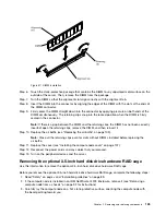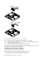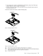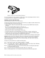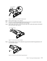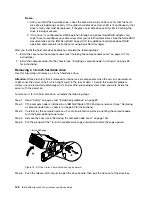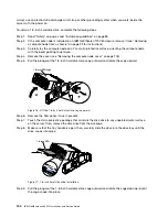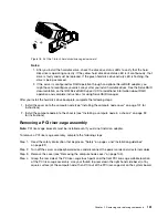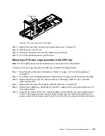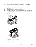
Step 4.
Slide the hard disk drive into the bay until it is firmly seated in the connector.
Step 5.
Lock the hard disk drive into place by closing the release lever.
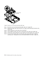
After you install the hard disk drive backplate, complete the following steps:
1. Install the cover onto the compute node (see “Installing the compute node cover” on page 107 for
instructions).
2. Install the compute node into the chassis (see “Installing a compute node in a chassis” on page 93
for instructions).
Removing and installing drives
Use this information to remove and install drives.
The following notes describe the type of hard disk drives that the server supports and other information
that you must consider when you install a hard disk drive. For a list of supported hard disk drives, see
http://www.ibm.com/systems/info/x86servers/serverproven/compat/us.
• Locate the documentation that comes with the hard disk drive and follow those instructions in addition to
the instructions in this chapter.
• Make sure that you have all the cables and other equipment that are specified in the documentation that
comes with the drive.
• Select the bay in which you want to install the drive.
• Check the instructions that come with the drive to determine whether you have to set any switches or
jumpers on the drive. If you are installing a SAS or SATA hard disk drive, be sure to set the SAS or
SATA ID for that device.
• The compute node supports up to one 3.5-inch, two 2.5-inch, or four 1.8-inch easy-swap SAS or SATA
hard disk drives.
• For a complete list of supported optional devices for the server, see
http://www.ibm.com/systems/info/x86servers/serverproven/compat/us.
Removing a 3.5-inch hard disk drive
Use this information to remove a 3.5-inch SAS/SATA hard disk drive.
To remove a 3.5-inch SAS/SATA hard disk drive, complete the following steps.
Step 1.
Read “Safety” on page v and “Installation guidelines” on page 89.
Step 2.
If the compute node is installed in an IBM NeXtScale n1200 Enclosure, remove it (see “Removing
a compute node from a chassis” on page 92 for instructions).
Step 3.
Carefully lay the compute node on a flat, static-protective surface, orienting the compute node
with the bezel pointing toward you.
Step 4.
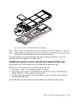
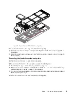
Remove the cover (see “Removing the compute node cover” on page 105).
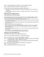
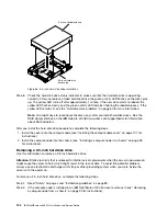
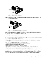
Step 5.
Press down the release latch.
Step 6.
Push outward and lift the hard disk drive out of the bay.
142
IBM NeXtScale nx360 M4 Installation and Service Guide
Summary of Contents for NeXtScale nx360 M4
Page 1: ...IBM NeXtScale nx360 M4 Installation and Service Guide Machine Type 5455 ...
Page 6: ...iv IBM NeXtScale nx360 M4 Installation and Service Guide ...
Page 34: ...20 IBM NeXtScale nx360 M4 Installation and Service Guide ...
Page 58: ...44 IBM NeXtScale nx360 M4 Installation and Service Guide ...
Page 94: ...80 IBM NeXtScale nx360 M4 Installation and Service Guide ...
Page 192: ...178 IBM NeXtScale nx360 M4 Installation and Service Guide ...
Page 538: ...524 IBM NeXtScale nx360 M4 Installation and Service Guide ...
Page 562: ...548 IBM NeXtScale nx360 M4 Installation and Service Guide ...
Page 722: ......
Page 730: ......
Page 737: ......
Page 738: ...Part Number 00KC216 Printed in China 1P P N 00KC216 1P00KC216 ...


