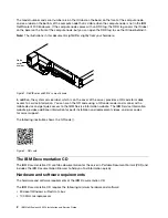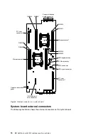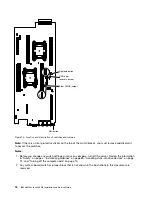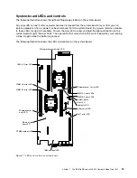
Use this connector to connect the server to a network for full systems-management information control.
This connector is used only by the Integrated Management Module II (IMM2). A dedicated management
network provides additional security by physically separating the management network traffic from the
production network. You can use the Setup utility to configure the server to use a dedicated systems
management network or a shared network.
Console breakout cable
Use this information for details about the console breakout cable.
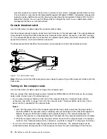
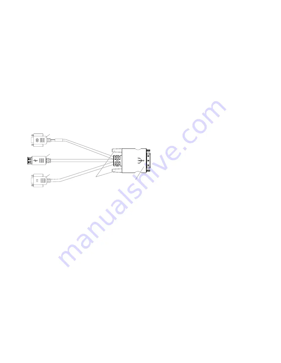
Use the console breakout cable to connect external I/O devices to the compute node. The console breakout
cable connects through the KVM connector (see “Compute node controls, connectors, and LEDs” on page
12). The console breakout cable has connectors for a display device (video), two USB connectors for a USB
keyboard and mouse, and a serial interface connector.
The following illustration identifies the connectors and components on the console breakout cable.
Serial
connector
USB
ports (2)
VGA
connector
KVM connector
Captive
screws
Figure 7. Console breakout cable
Note:
When you install the KVM cable, gently press down the pull out tag a little to prevent interfere with the
KVM cable.
Turning on the compute node
Use this information for details about turning on the compute node.
After you connect the compute node to power through the IBM NeXtScale n1200 Enclosure, the compute
node can be started in any of the following ways:
• You can press the power button on the front of the compute node (see “Compute node controls,
connectors, and LEDs” on page 12) to start the compute node. The power button works only if local
power control is enabled for the compute node.
Notes:
1. Wait until the power LED on the compute node flashes slowly before you press the power button.
While the IMM2 in the compute node is initializing and synchronizing with the Chassis Management
Module, the power LED flashes rapidly, and the power button on the compute node does not
respond. This process can take approximately 90 seconds after the compute node has been installed.
2. While the compute node is starting, the power LED on the front of the compute node is lit and does
not flash. See “Compute node controls, connectors, and LEDs” on page 12 for the power LED states.
• You can turn on the compute node through the Wake on LAN feature. The compute node must be
connected to power (the power LED is flashing slowly) and must be communicating with the Chassis
14
IBM NeXtScale nx360 M4 Installation and Service Guide
Summary of Contents for NeXtScale nx360 M4
Page 1: ...IBM NeXtScale nx360 M4 Installation and Service Guide Machine Type 5455 ...
Page 6: ...iv IBM NeXtScale nx360 M4 Installation and Service Guide ...
Page 34: ...20 IBM NeXtScale nx360 M4 Installation and Service Guide ...
Page 58: ...44 IBM NeXtScale nx360 M4 Installation and Service Guide ...
Page 94: ...80 IBM NeXtScale nx360 M4 Installation and Service Guide ...
Page 192: ...178 IBM NeXtScale nx360 M4 Installation and Service Guide ...
Page 538: ...524 IBM NeXtScale nx360 M4 Installation and Service Guide ...
Page 562: ...548 IBM NeXtScale nx360 M4 Installation and Service Guide ...
Page 722: ......
Page 730: ......
Page 737: ......
Page 738: ...Part Number 00KC216 Printed in China 1P P N 00KC216 1P00KC216 ...


