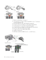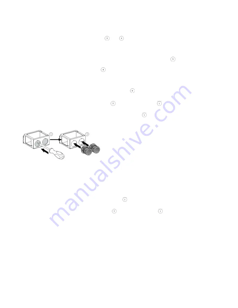
10.
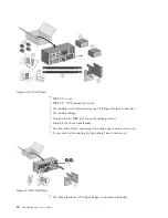
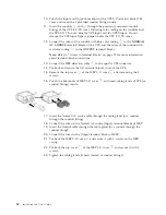
Punch the Input and Output knockouts of the UPS I/O terminal block (TB)
cover and insert the 2 provided conduit fittings inside.
11.
Insert the conduits
and
through the previously mounted conduit
fittings of the UPS I/O TB cover, following color coding on the conduits and
the UPS I/O TB cover: blue for UPS Input; red for UPS Output. Do not
remove the UPS Input Bypass jumper inside the UPS I/O TB cover.
12.
Connect the wires of the conduit with blue color coding
to the
NORMAL
AC SOURCE
terminal blocks of the UPS, and the wires of the conduit with
red color coding
to the
OUTPUT
terminal blocks.
Note:
Refer to “Access to terminal blocks” on page 27 for more information
about terminal-block connections.
13.
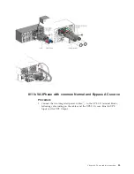
Connect the MBP detection cable
to the specific UPS connector.
14.
Put back and secure the I/O terminal blocks cover of the UPS.
15.
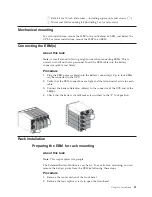
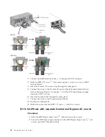
Remove the top cover
of the MBP I/O cover
after removing the 3
screws.
16.
Punch the knockouts of MBP I/O cover
and insert cable glands of UPS (or
conduit fittings) inside.
17.
Insert the Normal AC source cable through the cable gland (or a conduit
through the conduit fitting).
18.
Connect the wires to the Normal AC source (Input) terminal blocks of MBP.
19.
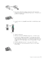
Insert the Output cable through the cable gland (or a conduit through the
conduit fitting).
20.
Connect the wires to the Output terminal blocks of MBP.
21.
Put back the MBP I/O cover
and secure it with 4 screws on the MBP
casing.
22.
Put back the top cover
of the MBP I/O cover
and secure it with 3
screws.
23.
Tighten the cable glands (if used instead of conduit fittings).
32
Installation and User's Guide
Summary of Contents for RT11.0VA
Page 2: ......
Page 18: ...xvi Installation and User s Guide ...
Page 22: ...4 Installation and User s Guide ...
Page 86: ...68 Installation and User s Guide ...
Page 98: ...80 Installation and User s Guide ...
Page 100: ...82 Installation and User s Guide ...
Page 101: ......
Page 102: ...Part Number 00WA361 Printed in USA 1P P N 00WA361 ...

