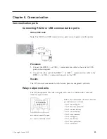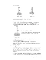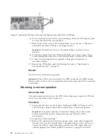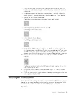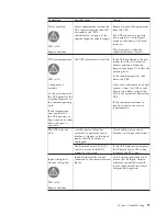
RPO connections:
Normally closed
Normally open
Terminal wire size rating is 0.32-4 mm
2
(22-12 AWG).
Remote control connection and test
1.
Ensure that the UPS is shut down and the utility power is disconnected.
2.
Remove the RPO connector from the UPS by loosening the screws.
3.
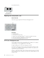
Connect a normally closed volt-free contact between pins 1 and 3 of the
connector.
Contact open: shut down of UPS
To return to normal operation, close the external remote shut
down contact and restart the UPS from the front panel.
Normally closed
4.
Plug the RPO connector into the back of the UPS and fix the screws.
5.
Connect and restart the UPS.
6.
Open the external remote shut down contact to test the function.
Note:
Always test the RPO function before applying your critical load to avoid
accidental load loss.
Connectivity card
The UPS Network Management Card allows the UPS to communicate in Ethernet
environments. The card has SNMP and HTTP capabilities as well as monitoring
through a Web browser interface. In addition, a Environmental Monitoring Probe
can be attached to obtain humidity, temperature, smoke alarm, and security
information.
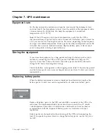
The unit has one available communication bay for the UPS Network Management
Card. See “Preparing the EBM for rack mounting” on page 21 for the location of
Chapter 6. Communication
45
Summary of Contents for RT11.0VA
Page 2: ......
Page 18: ...xvi Installation and User s Guide ...
Page 22: ...4 Installation and User s Guide ...
Page 86: ...68 Installation and User s Guide ...
Page 98: ...80 Installation and User s Guide ...
Page 100: ...82 Installation and User s Guide ...
Page 101: ......
Page 102: ...Part Number 00WA361 Printed in USA 1P P N 00WA361 ...


