64
LED descriptions
NOTE:
For information about supported combinations of host interface protocols using CNC ports, see
CNC ports
used for host connection
on page 10 and the “Configuring host ports topic” in the Storage Management Guide.
1
When in FC mode, the SFPs must be a qualified 8 Gb or 16 Gb fibre optic option. A 16 Gbit/s SFP can run at 16 Gbit/s, 8 Gbit/s,
4 Gbit/s, or auto-negotiate its link speed. An 8 Gbit/s SFP can run at 8 Gbit/s, 4 Gbit/s, or auto-negotiate its link speed.
2
When in 1 GbE iSCSI mode, the SFPs must be a qualified 1 GbE iSCSI optic option.
3
When powering up and booting, iSCSI LEDs will be on/blinking momentarily, then they will switch to the mode of operation.
4
When port is down, both LEDs are off.
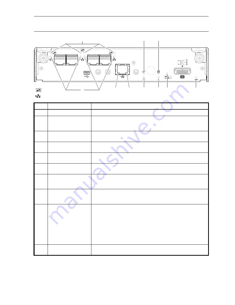
Figure 40
LEDs: S3200 CNC controller module (1 Gb RJ-45 SFPs)
LED
Description
Definition
1
Not used in example
1
The FC SFP is not shown in this example (see
Figure 39
on page 63).
2
Host 1 Gb iSCSI
2,3
Link Status/
Link Activity
Off — No link detected.
Green — The port is connected and the link is up.
Blinking green — The link has I/O activity.
3
Network Port Link
Active Status
4
Off — The Ethernet link is not established, or the link is down.
Green — The Ethernet link is up (applies to all negotiated link speeds).
4
Network Port Link Speed
4
Off — Link is up at 10/100base-T negotiated speeds.
Amber — Link is up and negotiated at 1000base-T.
5
OK to Remove
Off — The controller module is not prepared for removal.
Blue — The controller module is prepared for removal.
6
Unit Locator
Off — Normal operation.
Blinking white — Physically identifies the controller module.
7
CRU OK
Off — Controller module is not OK.
Blinking green — System is booting.
Green — Controller module is operating normally.
8
Fault/Service Required
Amber — A fault has been detected or a service action is required.
Blinking amber — Hardware-controlled power-up or a cache flush or restore
error.
9
Cache Status
Green — Cache is dirty (contains unwritten data) and operation is normal.
The unwritten information can be log or debug data that remains in the
cache, so a Green cache status LED does not, by itself, indicate that any user
data is at risk or that any action is necessary.
Off — In a working controller, cache is clean (contains no unwritten data).
This is an occasional condition that occurs while the system is booting.
Blinking green — A CompactFlash flush or cache self-refresh is in progress,
indicating cache activity.
See also
Cache Status LED details
on page 69.
10
Expansion Port Status
Off — The port is empty or the link is down.
On — The port is connected and the link is up.
CACHE
CLI
CLI
LINK
ACT
6Gb/s
SERVICE−1
SERVICE−2
PORT 0
PORT 1
PORT 2
PORT 3
= FC LEDs
= iSCSI LEDs
1
5
7
2
3
4
6
8
9
10


