


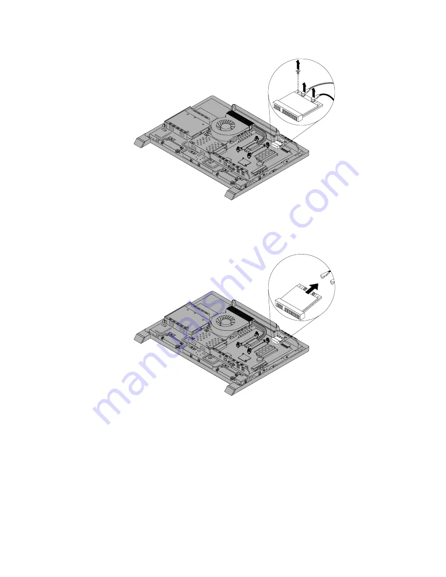
Figure 39. Removing the screw that secures the Wi-Fi card
8. Pivot the Wi-Fi card upward and lift the Wi-Fi card out of the mini PCI Express slot.
Figure 40. Removing the Wi-Fi card
9. Insert the notched end of the new Wi-Fi card into the mini PCI Express slot. Press the new Wi-Fi
card firmly, and then pivot the Wi-Fi card to align the screw hole in the new Wi-Fi card with that in
the computer main bracket.
10. Install the screw to secure the new Wi-Fi card.
11. Connect the two cables to the new Wi-Fi card.
12. Reinstall the system board shield. See “Removing and reinstalling the system board shield” on page 76.
13. Go to “Completing the parts replacement” on page 96.
Chapter 9
.
Replacing FRUs
95
Summary of Contents for S710
Page 1: ...Lenovo S710 All In One Hardware Maintenance Manual Machine Types 10152 F0AG ...
Page 2: ......
Page 3: ...Lenovo S710 All In One Hardware Maintenance Manual Machine Types 10152 F0AG ...
Page 8: ...2 Lenovo S710 All In OneHardware Maintenance Manual ...
Page 15: ...Chapter 2 Safety information 9 ...
Page 19: ...Chapter 2 Safety information 13 ...
Page 20: ...1 2 14 Lenovo S710 All In OneHardware Maintenance Manual ...
Page 21: ...1 2 Chapter 2 Safety information 15 ...
Page 26: ...1 2 20 Lenovo S710 All In OneHardware Maintenance Manual ...
Page 27: ...1 2 Chapter 2 Safety information 21 ...
Page 30: ...24 Lenovo S710 All In OneHardware Maintenance Manual ...
Page 34: ...28 Lenovo S710 All In OneHardware Maintenance Manual ...
Page 66: ...60 Lenovo S710 All In OneHardware Maintenance Manual ...
Page 70: ...Figure 3 Locating major FRUs and CRUs 64 Lenovo S710 All In OneHardware Maintenance Manual ...
Page 104: ...98 Lenovo S710 All In OneHardware Maintenance Manual ...
Page 117: ......
Page 118: ......


