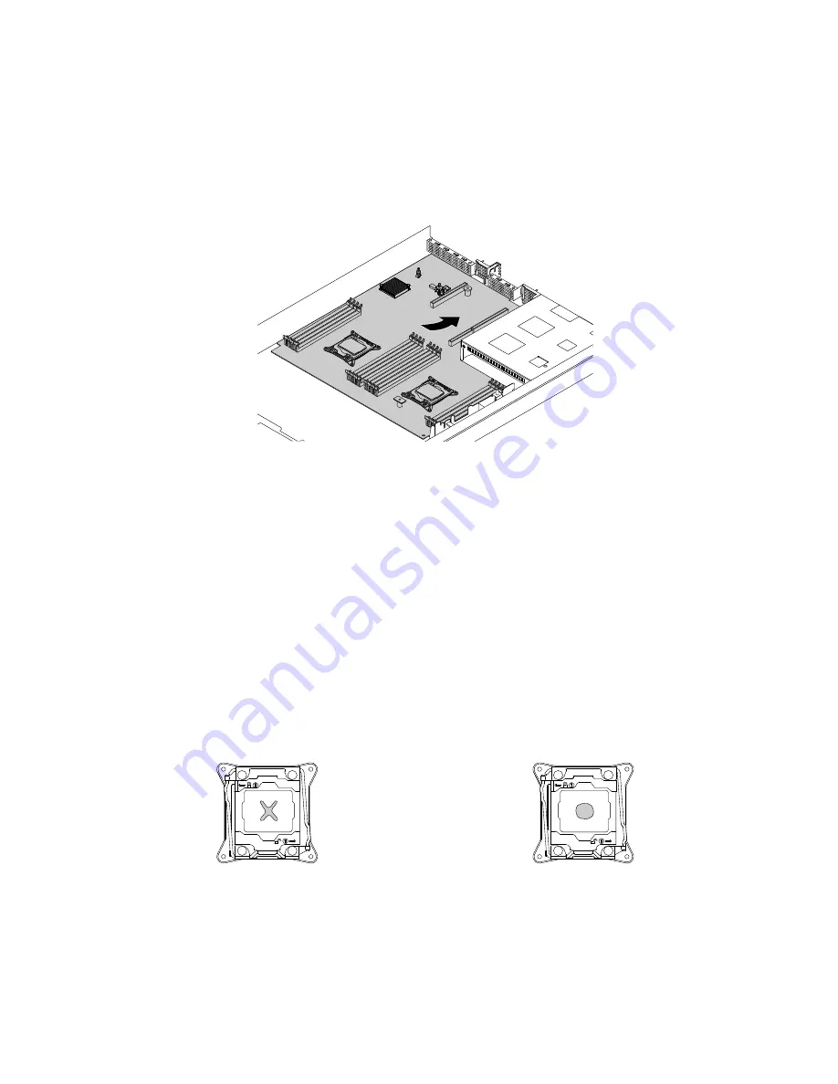
15. Install the new system board into the chassis and press the system board to the rear of the storage
product. Ensure that:
• The new system board is engaged by the mounting stud on the chassis.
• The rear connectors on the new system board are inserted into the corresponding holes in the
rear panel.
Figure 91. Installing the system board
16. Remove the microprocessors from the old system board and install them on the new system board. See
“Installing or replacing the microprocessor” on page 74.
Note:
Do not drop anything onto the microprocessor socket on the old system board while it is exposed.
The socket pins must be kept as clean as possible.
17. Use a cleaning pad to wipe the thermal grease from the heat sinks and the top of the microprocessors.
Dispose of the cleaning pad after all of the thermal grease is removed.
18. Use one of the following methods to apply appropriate amount of thermal grease to the top of the
microprocessors in the shape of a cross or a circle as shown. Either too much or too less application of
thermal grease can cause a thermal problem due to imperfect contact with the components.
Notes:
• Do not touch the thermal grease.
• Keep the thermal grease off the system board.
Figure 92. Applying the thermal grease to the top of the microprocessor
19. Install the heat sinks on the new system board. See “Installing or replacing a heat sink” on page 72.
110
Lenovo Storage N3310 User Guide and Hardware Maintenance Manual
Summary of Contents for Storage N3310
Page 1: ...Lenovo Storage N3310 User Guide and Hardware Maintenance Manual Machine Types 70FX and 70FY ...
Page 14: ...xii Lenovo Storage N3310 User Guide and Hardware Maintenance Manual ...
Page 18: ...4 Lenovo Storage N3310 User Guide and Hardware Maintenance Manual ...
Page 20: ...6 Lenovo Storage N3310 User Guide and Hardware Maintenance Manual ...
Page 138: ...124 Lenovo Storage N3310 User Guide and Hardware Maintenance Manual ...
Page 151: ......
Page 152: ......


