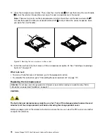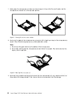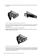
12. Close the microprocessor retainer. Close the small handle
1
first. Then, close the small handle
2
to
lock the retainer into position and secure the new microprocessor in the socket.
Note:
There are two marks on the microprocessor retainer. Ensure that you close the small handle
marked with
first and then close the small handle marked with
. Always follow the correct sequence
when you close the small handles.
Figure 55. Securing the microprocessor in the socket
13. Use a cleaning pad to wipe the thermal grease from the removed heat sink. Dispose of the cleaning
pad after all of the thermal grease is removed.
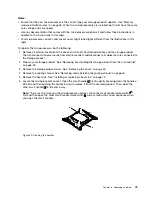
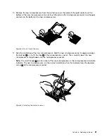
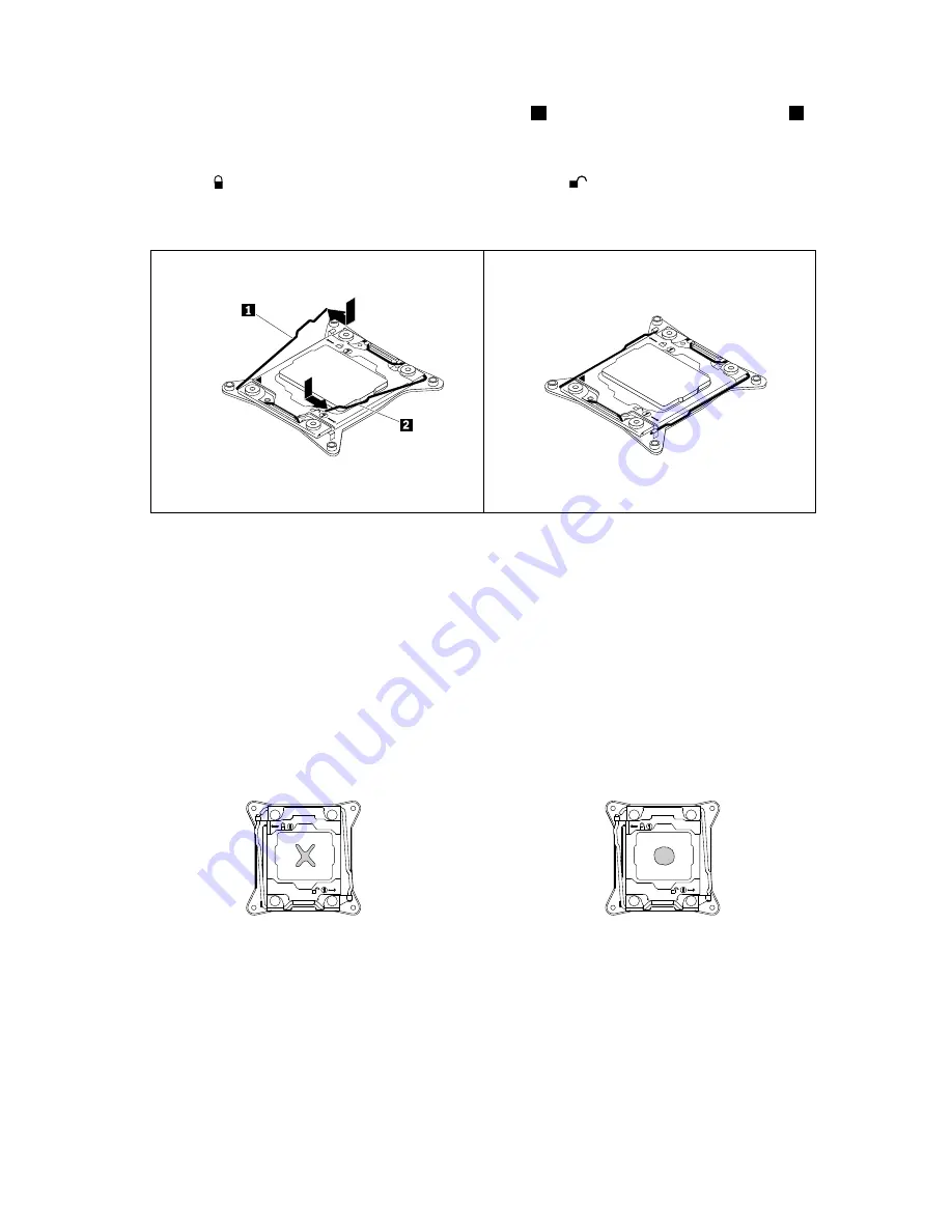
14. Use one of the following methods to apply appropriate amount of thermal grease to the top of the
newly installed microprocessor in the shape of a cross or a circle as shown. Either too much or too
less application of thermal grease can cause a thermal problem due to imperfect contact with the
components.
Notes:
• Do not touch the thermal grease.
• Keep the thermal grease off the system board.
Figure 56. Applying the thermal grease to the top of the microprocessor
15. Reinstall the heat sink. See “Installing or replacing a heat sink” on page 72.
16. If you are instructed to return the old microprocessor, follow all packaging instructions and use any
packaging materials that are supplied to you for shipping.
What to do next:
• To work with another piece of hardware, go to the appropriate section.
82
Lenovo Storage N3310 User Guide and Hardware Maintenance Manual
Summary of Contents for Storage N3310
Page 1: ...Lenovo Storage N3310 User Guide and Hardware Maintenance Manual Machine Types 70FX and 70FY ...
Page 14: ...xii Lenovo Storage N3310 User Guide and Hardware Maintenance Manual ...
Page 18: ...4 Lenovo Storage N3310 User Guide and Hardware Maintenance Manual ...
Page 20: ...6 Lenovo Storage N3310 User Guide and Hardware Maintenance Manual ...
Page 138: ...124 Lenovo Storage N3310 User Guide and Hardware Maintenance Manual ...
Page 151: ......
Page 152: ......


