Step 5.
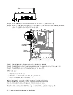
Connect the DVD cable into the connector on the rear of the optical drive cage.
Step 6.
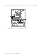
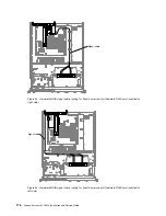
Route the DVD signal cable through the fan cage hole on the left of fan 1. The following illustration
shows the cable routing for the DVD signal cable.
00000000000
DVD drive SATA
signal cable
DVD drive
power cable
Step 7.
Secure the cable in the server using the cable tie and cable clip.
Step 8.
Reinstall the air baffle if it was removed before (see “Replacing the air baffle” on page 135).
Step 9.
Reinstall the cover (see “Replacing the cover” on page 132).
What to do next
1. Slide the server into the rack.
2. Reconnect the power cords and cables that you removed.
3. Turn on all attached devices and the server.
Removing the operator information panel assembly
Use this information to remove the operator information panel assembly.
Read the safety information in “Safety” on page v and “Installation guidelines” on page 33.
170
Lenovo System x3250 M4 Installation and Service Guide
Summary of Contents for System x3250 M4
Page 1: ...Lenovo System x3250 M4 Installation and Service Guide Machine Type 2583 ...
Page 6: ...iv Lenovo System x3250 M4 Installation and Service Guide ...
Page 74: ...60 Lenovo System x3250 M4 Installation and Service Guide ...
Page 98: ...84 Lenovo System x3250 M4 Installation and Service Guide ...
Page 136: ...122 Lenovo System x3250 M4 Installation and Service Guide ...
Page 144: ...130 Lenovo System x3250 M4 Installation and Service Guide ...
Page 418: ...404 Lenovo System x3250 M4 Installation and Service Guide ...
Page 596: ...582 Lenovo System x3250 M4 Installation and Service Guide ...
Page 604: ...Taiwan BSMI RoHS declaration 590 Lenovo System x3250 M4 Installation and Service Guide ...
Page 612: ...598 Lenovo System x3250 M4 Installation and Service Guide ...
Page 613: ......
Page 614: ......

