•
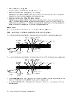
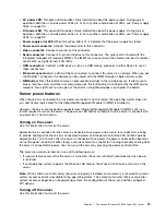
AC power LED:
This green LED provides status information about the power supply. During typical
operation, both the ac and dc power LEDs are lit. For any other combination of LEDs, see “Power-supply
LEDs” on page 93.
•
DC power LED:
This green LED provides status information about the power supply. During typical
operation, both the ac and dc power LEDs are lit. For any other combination of LEDs, see “Power-supply
LEDs” on page 93.
•
Power supply error LED:
When this yellow LED is lit, it indicates that the power supply has failed.
•
Power cord connector:
Connect the power cord to this connector.
•
Video connector:
Connect a monitor to this connector.
•
Serial connector:
Connect a 9-pin serial device to this connector. The serial port is shared with the
integrated management module II (IMM2). The IMM2 can take control of the shared serial port to redirect
serial traffic, using Serial over LAN (SOL).
•
USB connectors:
Connect a USB device, such as a USB mouse, keyboard, or other device to any of
these connectors.
•
Ethernet connectors:
Use either of these connectors to connect the server to a network. When you use
the Ethernet 1 connector, the network can be shared with the IMM2 through a single network cable.
•
NMI button:
Press this button to force a nonmaskable interrupt to the microprocessor. It allows you to
blue screen the server and take a memory dump (use this button only when directed by the IBM service
support). You might have to use a pen or the end of a straightened paper clip to press the button.
Server power features
When the server is connected to an ac power source but is not turned on, the operating system does not
run, and all core logic except for the Integrated Management Module II (IMM2) is shutdown.
However, the server can respond to requests from Integrated Management Module II (IMM2), such as a
remote request to turn on the server. The power-on LED flashes to indicate that the server is connected to
ac power but is not turned on.
Turning on the server
Use this information to turn on the server.
Approximately 5 seconds after the server is connected to ac power, one or more fans might start running
to provide cooling while the server is connected to power and the power-on button LED will blink quickly.
Approximately 1 to 3 minutes after the server is connected to ac power, the power-control button becomes
active (the power-on LED will blink slowly), and one or more fans might start running to provide cooling while
the server is connected to power. You can turn on the server by pressing the power-control button.
The server can also be turned on in any of the following ways:
• If a power failure occurs while the server is turned on, the server will restart automatically when power
is restored.
• If your operating system supports the Wake on LAN feature, the Wake on LAN feature can turn on the
server.
Note:
When 4 GB or more of memory (physical or logical) is installed, some memory is reserved for various
system resources and is unavailable to the operating system. The amount of memory that is reserved for
system resources depends on the operating system, the configuration of the server, and the configured
PCI options.
Turning off the server
Use this information to turn off the server.
.
The Lenovo System x3250 M4 Type 2583 server
15
Summary of Contents for System x3250 M4
Page 1: ...Lenovo System x3250 M4 Installation and Service Guide Machine Type 2583 ...
Page 6: ...iv Lenovo System x3250 M4 Installation and Service Guide ...
Page 74: ...60 Lenovo System x3250 M4 Installation and Service Guide ...
Page 98: ...84 Lenovo System x3250 M4 Installation and Service Guide ...
Page 136: ...122 Lenovo System x3250 M4 Installation and Service Guide ...
Page 144: ...130 Lenovo System x3250 M4 Installation and Service Guide ...
Page 418: ...404 Lenovo System x3250 M4 Installation and Service Guide ...
Page 596: ...582 Lenovo System x3250 M4 Installation and Service Guide ...
Page 604: ...Taiwan BSMI RoHS declaration 590 Lenovo System x3250 M4 Installation and Service Guide ...
Page 612: ...598 Lenovo System x3250 M4 Installation and Service Guide ...
Page 613: ......
Page 614: ......

