Note:
Before you install optional hardware, make sure that the server is working correctly. Start the server,
and make sure that the operating system starts, if an operating system is installed, or that a 19990305
error code is displayed, indicating that an operating system was not found but the server is otherwise
working correctly.
To remove the server cover, complete the following steps.
Step 1.
Read the safety information that begins in the begin of this documentation.
Step 2.
Turn off the server and peripheral devices and disconnect the power cords and all external cables,
if necessary.
Step 3.
If the server has been installed in a rack, loosen the two thumbscrews on the front of the server and
remove the server out of the rack enclosure; then, place it on a flat, static-protective surface.
Note:
When you disconnect the power source from the server, you lose the ability to view the LEDs
because the LEDs are not lit when the power source is removed. Before you disconnect the power
source, make a note of which LEDs are lit, including the LEDs that are lit on the front panel, on
the rear panel, and LEDs inside the server on the system board, then, see this documentation for
information about how to solve the problem.
Step 4.
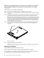
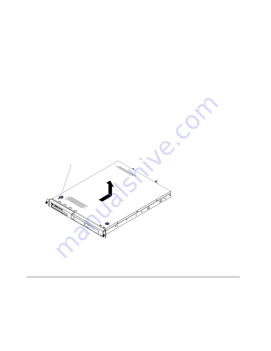
Press down firmly on the blue tab on the top of the cover (on the right side near the front of the
server) and slide the cover toward the rear of the server until the cover has disengaged from
the chassis.
00000000
00000000
00000000
00000000
00000000
0000
0000
0000
0000
0000
0000
000
000
000
Cover-release
button
Figure 8. Cover removal
Step 5.
Lift the cover off the server and set it aside.
Attention:
For proper cooling and airflow, replace the server cover before you turn on the server.
Removing the air baffle
Use this information to remove the air baffle from the server.
Read the safety information in “Safety” on page v and “Installation guidelines” on page 33.
If you are replacing a server component or an optional device in the server, you need to turn off the server
and peripheral devices, and disconnect the power cords and all external cables.
36
Lenovo System x3250 M4 Installation and Service Guide
Summary of Contents for System x3250 M4
Page 1: ...Lenovo System x3250 M4 Installation and Service Guide Machine Type 2583 ...
Page 6: ...iv Lenovo System x3250 M4 Installation and Service Guide ...
Page 74: ...60 Lenovo System x3250 M4 Installation and Service Guide ...
Page 98: ...84 Lenovo System x3250 M4 Installation and Service Guide ...
Page 136: ...122 Lenovo System x3250 M4 Installation and Service Guide ...
Page 144: ...130 Lenovo System x3250 M4 Installation and Service Guide ...
Page 418: ...404 Lenovo System x3250 M4 Installation and Service Guide ...
Page 596: ...582 Lenovo System x3250 M4 Installation and Service Guide ...
Page 604: ...Taiwan BSMI RoHS declaration 590 Lenovo System x3250 M4 Installation and Service Guide ...
Page 612: ...598 Lenovo System x3250 M4 Installation and Service Guide ...
Page 613: ......
Page 614: ......

