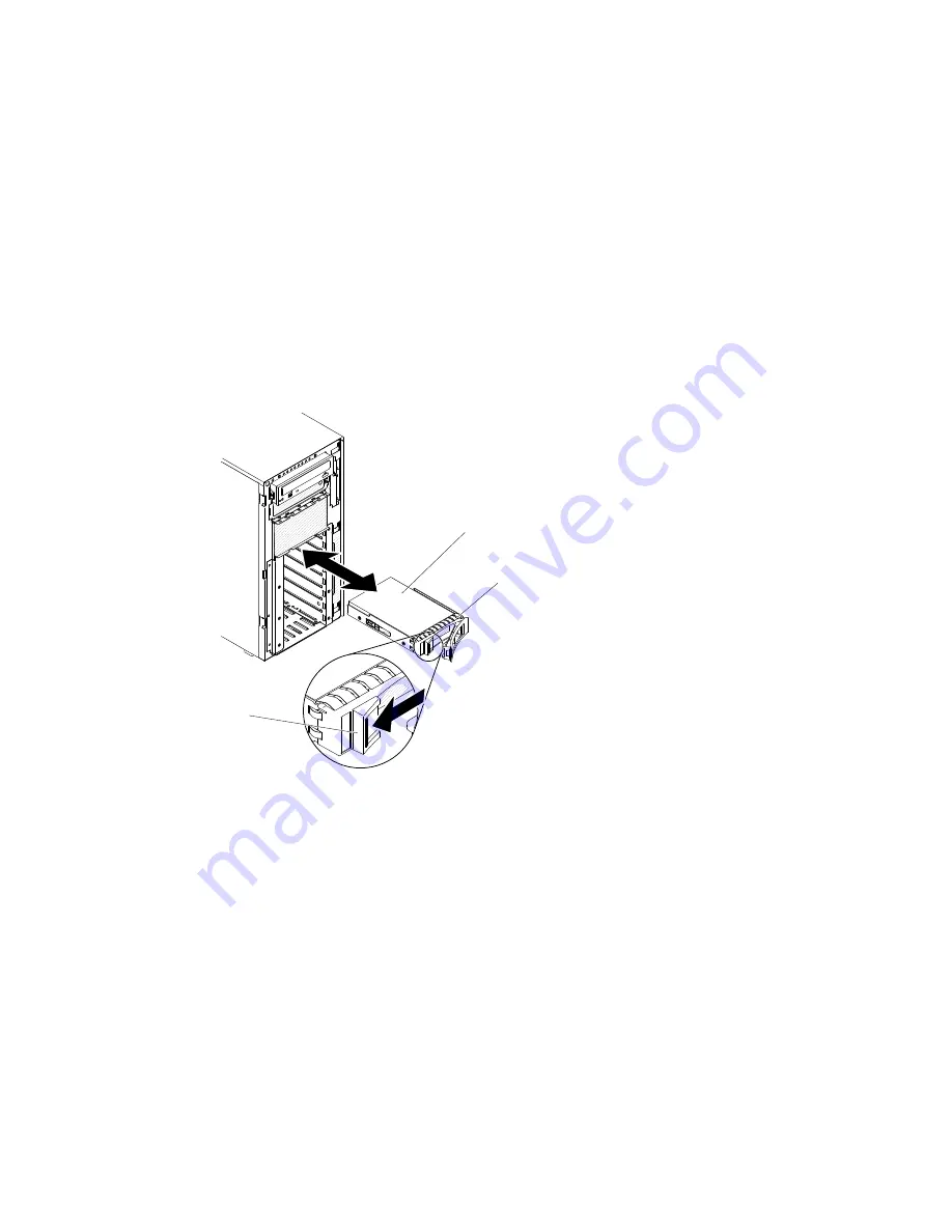
To install a 3.5-inch hot-swap SAS/SATA hard disk drive, complete the following steps.
Step 1.
Unlock the left-side cover.
Note:
You must unlock the left-side cover to open or remove the bezel. When you lock the left-side
cover, it locks both the cover and the bezel.
Step 2.
Open the bezel (see “Opening the bezel media door” on page 181).
Step 3.
Remove the filler panel, if one is present.
Step 4.
Touch the static-protective package that contains the disk drive to any unpainted metal surface on
the server; then, remove the disk drive from the package and place it on a static-protective surface.
Step 5.
Make sure that the drive tray handle is in the open position.
Step 6.
Align the drive assembly with the guide rails in the bay; then, carefully slide the drive assembly into
the drive bay until the drive snaps into place.
00
00
00
00
00
00
00
000000
000000
000000
000000
000000
000000
000000
00000
00000
00000
00000
000
000
00000
00000
00000
00000
Drive tray
Hot-swap
hard disk drive
Release
latch
Figure 117. Hot-swap hard disk drive installation
Step 7.
Rotate the drive tray handle to the closed position.
Step 8.
Check the hard disk drive status indicator to make sure that the hard disk drive is operating
correctly. After you replace a failed hard disk drive, the green activity LED flashes as the disk spins
up. The yellow LED turns off after approximately 1 minute. If the new drive starts to rebuild, the
yellow LED flashes slowly, and the green activity LED remains lit during the rebuild process. If the
yellow LED remains lit, see the “Hard disk drive problems” on page 149 for more information.
Note:
You might have to reconfigure the disk arrays after you install hard disk drives. See the
RAID documentation on the Lenovo website at http://www.lenovo.com/support for information
about RAID adapters.
Step 9.
Close the bezel (see “Closing the bezel media door” on page 183).
Step 10. Lock the left-side cover.
Removing a 3.5-inch simple-swap hard disk drive
Use this information to remove a 3.5-inch simple-swap hard disk drive.
Removing and replacing components
203
Summary of Contents for System x3500 M4
Page 1: ...System x3500 M4 Installation and Service Guide Machine Type 7383 ...
Page 6: ...iv System x3500 M4 Installation and Service Guide ...
Page 14: ...xii System x3500 M4 Installation and Service Guide ...
Page 140: ...126 System x3500 M4 Installation and Service Guide ...
Page 180: ...166 System x3500 M4 Installation and Service Guide ...
Page 194: ...180 System x3500 M4 Installation and Service Guide ...
Page 978: ...964 System x3500 M4 Installation and Service Guide ...
Page 1002: ...988 System x3500 M4 Installation and Service Guide ...
Page 1160: ...1146 System x3500 M4 Installation and Service Guide ...
Page 1164: ...1150 System x3500 M4 Installation and Service Guide ...
Page 1172: ...Taiwan BSMI RoHS declaration 1158 System x3500 M4 Installation and Service Guide ...
Page 1181: ......
Page 1182: ......


