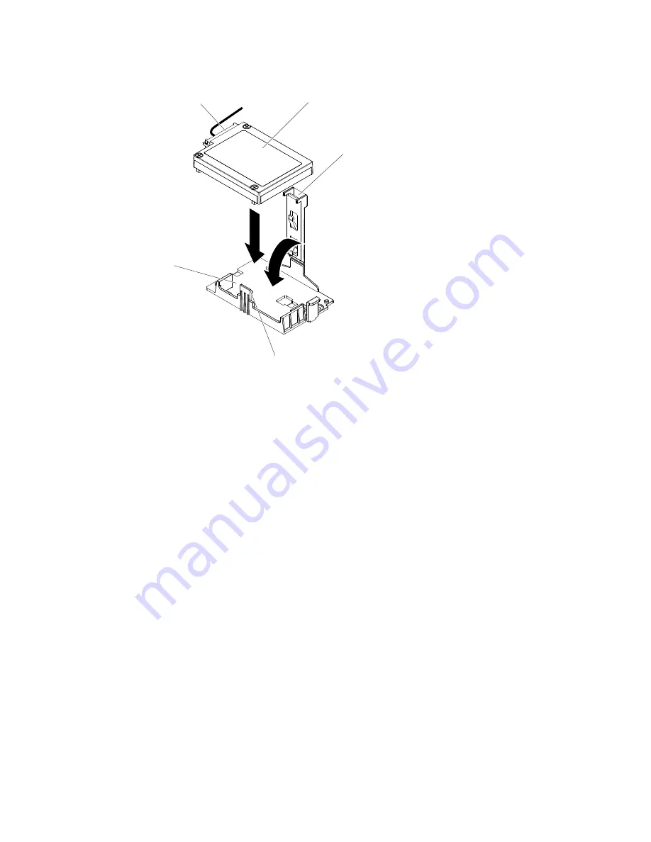
retention clip
Battery / flash power module
Battery / flash power module
Battery / flash power
module cable connector
Release
tab
Battery / flash power
module holder
Figure 136. Align the battery/flash power module cable connector
Note:
The positioning of the remote battery/flash power module depends on the type of the
remote batteries/flash power module that you install.
b.
Connect the other end of the battery/flash power module cable to the battery/flash power
module cable connector on the battery/flash power module.
c.
Lower and press down on the retention clip until it snaps in place to hold the battery/flash
power module firmly in place.
Step 7.
Install and lock the left-side cover (see “Installing the left-side cover” on page 185).
If you have replaced a server component or installed an optional device in the server, you need to reconnect
the power cords and all external cables, and turn on the server and peripheral devices.
Note:
You must wait approximately 3 minutes after you connect the server power cord to an electrical outlet
before the power-control button becomes active.
Removing an optional ServeRAID adapter memory module
Use this information to remove an optional ServeRAID adapter memory module.
Read the safety information in “Safety” on page v and “Installation guidelines” on page 35.
If you are replacing a server component in the server, you need to turn off the server and peripheral devices,
and disconnect the power cords and all external cables.
To remove an optional ServeRAID adapter memory module, complete the following steps.
Step 1.
Carefully turn the server on its side so that it is lying flat, with the cover facing up.
Attention:
Do not allow the server to fall over.
Removing and replacing components
223
Summary of Contents for System x3500 M4
Page 1: ...System x3500 M4 Installation and Service Guide Machine Type 7383 ...
Page 6: ...iv System x3500 M4 Installation and Service Guide ...
Page 14: ...xii System x3500 M4 Installation and Service Guide ...
Page 140: ...126 System x3500 M4 Installation and Service Guide ...
Page 180: ...166 System x3500 M4 Installation and Service Guide ...
Page 194: ...180 System x3500 M4 Installation and Service Guide ...
Page 978: ...964 System x3500 M4 Installation and Service Guide ...
Page 1002: ...988 System x3500 M4 Installation and Service Guide ...
Page 1160: ...1146 System x3500 M4 Installation and Service Guide ...
Page 1164: ...1150 System x3500 M4 Installation and Service Guide ...
Page 1172: ...Taiwan BSMI RoHS declaration 1158 System x3500 M4 Installation and Service Guide ...
Page 1181: ......
Page 1182: ......


