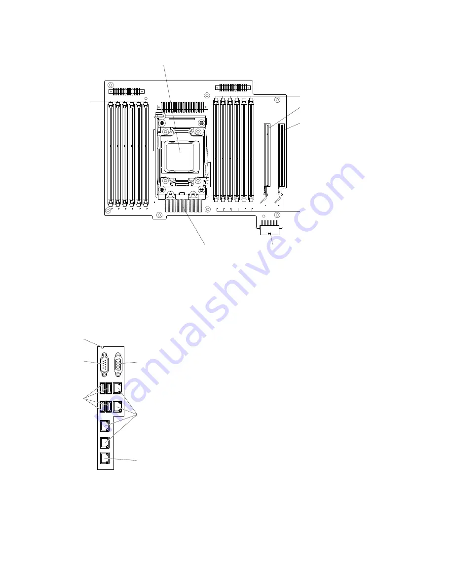
Microprocessor 2
DIMM 18-13
DIMM 24-19
PCI slot 7
PCI slot 8
Connector to
the system
board
System power 2
Figure 10. Internal connectors on microprocessor 2 expansion board
System-board external connectors
The following illustration shows the external connectors on the system board.
Video port
Serial port
NMI button
USB ports
Ethernet
System
management
Figure 11. External connectors on system board
System-board switches and jumpers
The following illustration shows the location and description of the switches and jumpers.
29
Summary of Contents for System x3500 M4
Page 1: ...System x3500 M4 Installation and Service Guide Machine Type 7383 ...
Page 6: ...iv System x3500 M4 Installation and Service Guide ...
Page 14: ...xii System x3500 M4 Installation and Service Guide ...
Page 140: ...126 System x3500 M4 Installation and Service Guide ...
Page 180: ...166 System x3500 M4 Installation and Service Guide ...
Page 194: ...180 System x3500 M4 Installation and Service Guide ...
Page 978: ...964 System x3500 M4 Installation and Service Guide ...
Page 1002: ...988 System x3500 M4 Installation and Service Guide ...
Page 1160: ...1146 System x3500 M4 Installation and Service Guide ...
Page 1164: ...1150 System x3500 M4 Installation and Service Guide ...
Page 1172: ...Taiwan BSMI RoHS declaration 1158 System x3500 M4 Installation and Service Guide ...
Page 1181: ......
Page 1182: ......


