background image

Lenovo TAB 2 A10-70 Hardware Maintenance Manual

26

This section presents notices related to removing and replacing parts. Read this 
section carefully before replacing any FRU.

Screw notices

Loose screws can cause a reliability problem. In Lenovo computers, this problem 
is addressed with special nylon-coated screws that have the following 
characteristics:
• They maintain tight connections.
• They do not easily come loose, even with shock or vibration.
• They are harder to tighten.
• Each one should be used only once.

Do the following when you service this machine:
• Keep the screw kit in your tool bag.
• Always use new screws.
• Use a torque screwdriver if you have one.

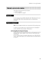
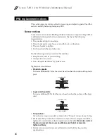
Tighten screws as follows:
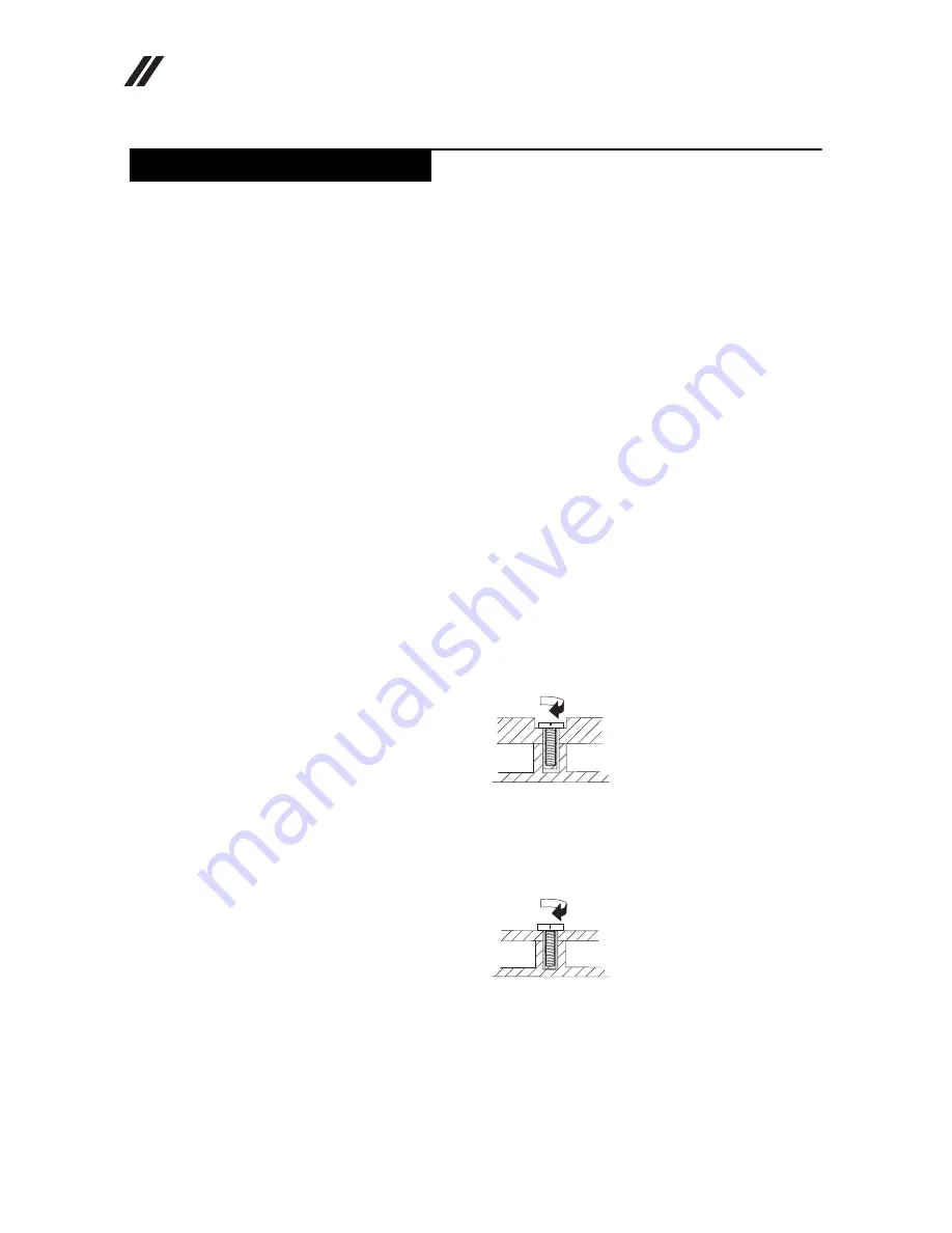
Plastic to plastic

Turn an additional 90° after the screw head touches the surface of the plastic 
part:

Logic card to plastic

Turn an additional 180° after the screw head touches the surface of the logic 
card:

Torque driver

If you have a torque screwdriver, refer to the “Torque” column for each step.

• Make sure that you use the correct screws. If you have a torque screwdriver, 

tighten all screws firmly to the torque shown in the table. 

Never use a screw 

that you removed. Use a new one. Make sure that all screws are 
tightened firmly

.

• Ensure torque screwdrivers are calibrated correctly following country 

specifications.

FRU replacement notices

more than 90°

(Cross-section)

more than 180°

(Cross-section)

Summary of Contents for TAB 2 A10-70

Page 1: ...Lenovo TAB 2 A10 70 Hardware Maintenance Manual ...

Page 2: ...veloped exclusively at private expense and are sold to governmental entities as commercial items as defined by 48 C F R 2 101 with limited and restricted rights to use reproduction and disclosure LIMITED AND RESTRICTED RIGHTS NOTICE If products data computer software or services are delivered pursuant to a General Services Administration GSA contract use reproduction or disclo sure is subject to r...

Page 3: ...rger 21 Checking the internal battery status 22 Related service information 23 Security 23 Power management 23 Activating Deactivating the Display 23 Lenovo TAB 2 A10 70 24 Specifications 24 FRU replacement notices 26 Screw notices 26 Removing and replacing an FRU 27 1010 Rear cover and side key 28 1020 Battery pack 30 1030 Rear camera 36 1040 Front camera 38 1050 LCD FPC 41 1060 Vibrator motor 46...

Page 4: ......

Page 5: ......

Page 6: ...cing computers The product specific section includes service reference and product specific parts information About this manual Note The information provided in this manual is applicable to both product versions mentioned above unless otherwise specified Important This manual is intended only for trained servicers who are familiar with Lenovo products Use this manual to troubleshoot problems effec...

Page 7: ...ervice a Lenovo computer General safety on page 2 Electrical safety on page 3 Safety inspection guide on page 5 Handling devices that are sensitive to electrostatic discharge on page 6 Grounding requirements on page 6 Safety notices multilingual translations on page 7 Laser compliance statement on page 14 Safety information ...

Page 8: ...ay from all personnel while you are servicing the machine Keep your toolcase away from walk areas so that other people will not trip it over Do not wear loose clothing that can be trapped in the moving parts of the machine Make sure that your sleeves are fastened or rolled up above your elbows If your hair is long fasten it Insert the ends of your necktie or scarf inside clothing or fasten it with...

Page 9: ...ck Attention An electrical shock can occur only when there is a complete circuit By observing the above rule you may prevent a current from passing through your body When using testers set the controls correctly and use the approved probe leads and accessories for that tester Stand on suitable rubber mats obtained locally if necessary to insulate you from grounds such as metal floor strips and mac...

Page 10: ...e of a plastic dental mirror The surface is conductive such touching can cause personal injury and machine damage Do not service the following parts with the power on when they are removed from their normal operating places in a machine Power supply units Pumps Blowers and fans Motor generators and similar units This practice ensures correct grounding of the units If an electrical accident occurs ...

Page 11: ... determine whether there are any potential unsafe conditions use the following checklist at the beginning of every service task Begin the checks with the power off and the power cord disconnected Checklist 1 Check exterior covers for damage loose broken or sharp edges 2 Turn off the computer Disconnect the power cord 3 Check the power cord for a A third wire ground connector in good condition Use ...

Page 12: ...e mat is especially useful when handling ESD sensitive devices Select a grounding system such as those listed below to provide protection that meets the specific service requirement Attach the ESD ground clip to any frame ground ground braid or green wire ground When working on a double insulated or battery operated system use an ESD common ground or reference point You can use coax or connector o...

Page 13: ... Austausch der Computer wieder angeschlossen wird muß sichergestellt werden daß keine Schrauben Federn oder andere Kleinteile fehlen oder im Gehäuse vergessen wurden Der Computer muß geschüttelt und auf Klappergeräusche geprüft werden Metallteile oder splitter können Kurzschlüsse erzeugen Prima di accendere l elaboratore dopo che é stata effettuata la sostituzione di una FRU accertarsi che tutte l...

Page 14: ...alten Sie darf nicht zerlegt wiederaufgeladen kurzgeschlossen oder Feuer oder Wasser ausgesetzt werden Bei der Entsorgung die örtlichen Bestimmungen für Sondermüll beachten Beim Ersetzen der Bereitschafts oder Systembatterie nur Batterien des Typs verwenden der in der Ersatzteilliste aufgeführt ist Der Einsatz falscher Batterien kann zu Entzündung oder Explosion führen Alcune batterie di riserva c...

Page 15: ...eschlossen oder Feuer oder Wasser ausgesetzt werden Bei der Entsorgung die örtlichen Bestimmungen für Sondermüll beachten Beim Ersetzen der Batterie nur Batterien des Typs verwenden der in der Ersatzteilliste aufgeführt ist Der Einsatz falscher Batterien kann zu Entzündung oder Explosion führen La batteria contiene piccole quantità di nichel Non smontarla gettarla nel fuoco o nell acqua né cortoci...

Page 16: ...ieses Typs dürfen nicht aufgeladen zerlegt über 100 C erhitzt oder verbrannt werden Auch darf ihr Inhalt nicht mit Wasser in Verbindung gebracht oder der zur richtigen Polung angebrachte Verbindungsstecker entfernt werden Bei der Entsorgung die örtlichen Bestimmungen für Sondermüll beachten Beim Ersetzen der Batterie nur Batterien des Typs verwenden der in der Ersatzteilliste aufgeführt ist Der Ei...

Page 17: ...ten Der LCD Bildschirm besteht aus Glas und kann zerbrechen wenn er unsachgemäß behandelt wird oder der Computer auf den Boden fällt Wenn der Bildschirm beschädigt ist und die darin befindliche Flüssigkeit in Kontakt mit Haut und Augen gerät sollten die betroffenen Stellen mindestens 15 Minuten mit Wasser abgespült und bei Beschwerden anschließend ein Arzt aufgesucht werden Nel caso che caso l LCD...

Page 18: ... battery can produce enough current to burn personnel or combustible materials Bien que le voltage des batteries principales soit peu élevé le court circuit ou la mise à la masse d une batterie peut produire suffisamment de courant pour brûler des matériaux combustibles ou causer des brûlures corporelles graves Obwohl Hauptbatterien eine niedrige Spannung haben können sie doch bei Kurzschluß oder ...

Page 19: ...et déconnectez tous les cordons d interface Die Stromzufuhr muß abgeschaltet alle Stromkabel aus der Steckdose gezogen der Akku entfernt und alle Verbindungskabel abgenommen sein bevor eine FRU entfernt wird Prima di rimuovere qualsiasi FRU spegnere il sistema scollegare dalle prese elettriche tutti i cavi di alimentazione rimuovere la batteria e poi scollegare i cavi di interconnessione Antes de ...

Page 20: ... device could result in exposure to hazardous laser radiation There are no serviceable parts inside those drives Do not open Laser compliance statement CAUTION Use of controls or adjustments or performance of procedures other than those specified herein might result in hazardous radiation exposure O uso de controles ajustes ou desempenho de procedimentos diferentes daqueles aqui especificados pode...

Page 21: ...luz Rayonnement laser si carter ouvert Évitez de fixer le faisceau de le regarder directement avec des instruments optiques ou de vous exposer au rayon Laserstrahlung bei geöffnetem Gerät Nicht direkt oder über optische Instrumente in den Laserstrahl sehen und den Strahlungsbereich meiden Kinyitáskor lézersugár Ne nézzen bele se szabad szemmel se optikai eszközökkel Kerülje a sugárnyalábbal való é...

Page 22: ...nd servicing FRUs If you are instructed to replace an FRU but the replacement does not solve the problem reinstall the original FRU before you continue Some computers have both a processor board and a system board If you are instructed to replace either of them and replacing one of them does not solve the problem reinstall that board and then replace the other one If an adapter or a device consist...

Page 23: ...itive Improper handling can cause damage to those components and may cause a system malfunction Attention When handling a system board Do not drop the system board or apply any excessive force to it Avoid rough handling of any kind Avoid bending the system board and hard pushing to prevent cracking at each BGA Ball Grid Array chipset ...

Page 24: ...ts suppliers to be ready to support Lenovo s requirements and schedule in the EU Products sold in 2005 and 2006 will contain some RoHS compliant FRUs The following statement pertains to these products and any product Lenovo produces containing RoHS compliant FRUs RoHS compliant FRUs have unique FRU part numbers Before or after the RoHS implementation date failed RoHS compliant parts must always be...

Page 25: ...ce might have been altered If you select an incorrect drive data or programs might be overwritten Replace an FRU only with another FRU of the correct model When you replace an FRU make sure that the machine model and the FRU part number are correct by referring to the FRU parts list An FRU should not be replaced just because of a single unreproducible failure Single failures can occur for a variet...

Page 26: ...ferring to the following list The following are not covered under warranty LCD panel cracked from the application of excessive force or from being dropped Scratched cosmetic parts Distortion deformation or discoloration of the cosmetic parts Plastic parts latches pins or connectors that have been cracked or broken by excessive force Damage caused by liquid spilled into the system Damage caused by ...

Page 27: ...e internal battery status on page 22 Checking the Computer AC Charger When you use the computer AC Charger to charge the tablet but no power is charged see the instructions in this topic to check the computer AC Charger To check the computer AC Charger do the following 1 Disconnect the micro USB cable from the tablet 2 Measure the output voltage across the connector marked B of the micro USB cable...

Page 28: ... Accurate information about the battery status To get the accurate information about the battery status of the tablet do the following 1 Open the Android Settings screen To open the Android Settings screen do either of the following From the main Home screen touch the Android Settings icon on Lenovo Launch Zone The Android Settings screen is displayed Pull down the application icon from the action...

Page 29: ...e power consumption the computer has three power management modes screen blank sleep standby and hibernation Activating Deactivating the Display With the display deactivated press the Power button on the computer to activate the display The computer display will then illuminate indicating that it has been activated If you do not need to use your computer temporarily you can press the Power button ...

Page 30: ... Description Size Weight Size 247mm x 171mm x 8 9mm Weight 509g System CPU Quad Core 1 5GHz 64bits Hardware Platform MT8732 MT8165 RAM LP DDR3 1866 2GB Storage Capacity 16GB 32GB LCD 10 1 1920 x 1200 pixels Integrated Camera Rear camera 8 0Mega pixels Auto Focus Front camera 5 0Mega pixels Fixed Focus Battery Li ion battery 7 000mAh Operating System Android 4 4 upgradable to new OS version Network...

Page 31: ... Communication WiFi 802 11a b g n GSM EDGE 850 900 1800 1900MHz WCDMA 2100 850 1900 900MHz LTE version only LTE Band 1 3 40 41 LTE version only for PRC market LTE Band 1 3 7 8 20 LTE version only for AP and EMEA market Bluetooth 4 0 A GPS support GPS FM radio Others Speaker Microphone Gravity sensor Vibration Hall sensor Dolby audio system DS1 WiFi Direct based on Android 4 4 WiFi Display ...

Page 32: ...l bag Always use new screws Use a torque screwdriver if you have one Tighten screws as follows Plastic to plastic Turn an additional 90 after the screw head touches the surface of the plastic part Logic card to plastic Turn an additional 180 after the screw head touches the surface of the logic card Torque driver If you have a torque screwdriver refer to the Torque column for each step Make sure t...

Page 33: ...en by the arrow in the figure 7 To put the new FRU in place reverse the removal procedures and follow any of the notes that pertain to replacement For information about connecting and arranging internal cables see Locations on page 68 8 When replacing an FRU use the correct screw as specified in the procedures Attention After replacing an FRU do not turn on the computer until you have made sure th...

Page 34: ...tablet in one hand and use a triangle paddle to unlock the rear cover from the tablet along the joint line as shown in the figure below Figure 1 1 Unlocking the rear cover from the front module along the joint line 2 Slowly remove the rear cover Figure 1 2 The removed rear cover with side key ...

Page 35: ...Lenovo TAB 2 A10 70 29 3 Remove the side key from the rear cover using a pair of pointed tweezer Figure 1 3 Removing the side key Figure 1 4 The removed rear cover and side key ...

Page 36: ...metal piece for fixing the battery FPC Part No Screw quantity Color Torque Phillips flat head screw M1 4 3 0 2 Silver N A CAUTION Risk of explosion if the battery is replaced with an incorrect type When replacing the lithium battery use only the same or an equivalent type that is recommended by the manufacturer The battery contains lithium and can explode if not properly used handled or disposed o...

Page 37: ... 31 2 Remove the metal piece using a pair of tweezers Figure 2 2 Removing the metal piece 3 Disconnect the battery FPC from its connector on the main board using a pair of tweezers Figure 2 3 Disconnecting the battery FPC ...

Page 38: ...FPC from the main board as shown in the figure below Figure 2 4 Detaching the battery FPC 5 Remove the conductive tape or mylar on the LCD FPC at the main board side as shown in the figure below Figure 2 5 Removing the conductive tape or mylar on the LCD FPC main board side ...

Page 39: ...PC on the main board using a triangle paddle Figure 2 6 Unlocking the connector of the LCD FPC main board side 7 Pull out the LCD FPC from its connector on the main board as shown in the figure below Figure 2 7 Pulling out the LCD FPC from the main board side ...

Page 40: ...LCD FPC from the front module of the tablet as shown in the figure below Figure 2 8 Detaching the LCD FPC 9 Detach the battery pack from its seat by inserting a thin flat blade into the joint surface as shown in the figure below Figure 2 9 Detaching the battery pack ...

Page 41: ...Lenovo TAB 2 A10 70 35 10 Remove the battery pack from the front module of the tablet Figure 2 10 Removing the battery pack Figure 2 11 The removed battery pack ...

Page 42: ...e 28 in 1010 Rear cover and side key Battery FPC see Step 1 on page 30 to Step 3 on page 31 in 1020 Battery pack 1 Detach the connector of the rear camera FPC from the main board using a pair of tweezers Figure 3 1 Detaching the connector of the rear camera FPC 2 Remove the rear camera from its seat as shown in the figure below Figure 3 2 Removing the rear camera ...

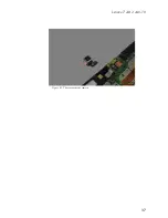
Page 43: ...Lenovo TAB 2 A10 70 37 Figure 3 3 The removed rear camera ...

Page 44: ...nd side key Battery FPC see Step 1 on page 30 to Step 3 on page 31 in 1020 Battery pack 1 Remove the conductive fabric tape on the front camera as shown in the figure below Figure 4 1 Removing the conductive fabric tape on the front camera 2 Detach the connector of the front camera FPC from the main board using a pair of tweezers Figure 4 2 Detaching the connector of the front camera FPC ...

Page 45: ...Lenovo TAB 2 A10 70 39 3 Remove the front camera from its seat as shown in the figure below Figure 4 3 Removing the front camera Figure 4 4 The removed front camera ...

Page 46: ...ery FPC see Step 1 on page 30 to Step 3 on page 31 in 1020 Battery pack 1 Remove the conductive tape or mylar on the LCD FPC at the main board side as shown in the figure below Figure 5 1 Removing the conductive tape or mylar on the LCD FPC main board side 2 Unlock the connector of the LCD FPC on the main board using a triangle paddle Figure 5 2 Unlocking the connector of the LCD FPC main board si...

Page 47: ...C from its connector on the main board as shown in the figure below Figure 5 3 Pulling out the LCD FPC from the main board side 4 Detach the LCD FPC from the front module of the tablet as shown in the figure below Figure 5 4 Detaching the LCD FPC ...

Page 48: ...PC at the front module side as shown in the figure below Figure 5 5 Removing the mylar on the LCD FPC front module side 6 Unlock the connector of the LCD FPC on the front module of the tablet using a triangle paddle Figure 5 6 Unlocking the connector of the LCD FPC front module side ...

Page 49: ... 2 A10 70 43 7 Pull out the main FPC from its connector on the front module of the tablet as shown in the figure below Figure 5 7 Pulling out the LCD FPC from the front module side Figure 5 8 The removed LCD FPC ...

Page 50: ...ver and side key Battery FPC see Step 1 on page 30 to Step 3 on page 31 in 1020 Battery pack 1 Desolder the wires of the vibrator motor from their connecting points on the main board at the position shown in the figure below Figure 6 1 Position for desoldering the wires of the vibrator motor 2 Remove the vibrator motor as shown in the figure below Figure 6 2 Removing the vibrator motor ...

Page 51: ...Lenovo TAB 2 A10 70 45 Figure 6 3 The removed vibrator motor ...

Page 52: ...nd side key Battery FPC see Step 1 on page 30 to Step 3 on page 31 in 1020 Battery pack 1 Desolder the wires of the microphone from their connecting points on the main board at the position shown in the figure below Figure 7 1 Position for desoldering the wires of the microphone 2 Remove the microphone from its rubber seat as shown in the figure below Figure 7 2 Removing the microphone ...

Page 53: ...Lenovo TAB 2 A10 70 47 Figure 7 3 The removed microphone ...

Page 54: ...ly see Step 1 on page 28 to Step 2 on page 28 in 1010 Rear cover and side key Battery FPC see Step 1 on page 30 to Step 3 on page 31 in 1020 Battery pack 1 Disconnect the antenna cable from its connector on the antenna PCB at the position as shown in the figure below Figure 8 1 Positions for disconnecting the antenna cable antenna PCB side ...

Page 55: ...re below Figure 8 2 The screws on the right speaker 3 Lift the right speaker and remove the antenna PCB using a pair of tweezers as shown in the figure below Figure 8 3 Removing the antenna PCB Part No Screw quantity Color Torque Phillips flat head screw M1 4 x 3 5 3 Black N A a a ...

Page 56: ...Lenovo TAB 2 A10 70 Hardware Maintenance Manual 50 Figure 8 4 The removed antenna LTE version only ...

Page 57: ...o Step 2 on page 28 in 1010 Rear cover and side key Battery FPC see Step 1 on page 30 to Step 3 on page 31 in 1020 Battery pack 1 Desolder the wires of the left speaker from their connecting points on the main board at the position shown in the figure below Figure 9 1 Position for desoldering the wires of the left speaker ...

Page 58: ...crews on the left speaker as shown in the figure below Figure 9 2 The screws on the left speaker 3 Remove the left speaker from the tablet Figure 9 3 Removing the left speaker Part No Screw quantity Color Torque Phillips flat head screw M1 4 x 3 5 3 Black N A a a ...

Page 59: ...Lenovo TAB 2 A10 70 53 Figure 9 4 The removed left speaker ...

Page 60: ...n 1010 Rear cover and side key Battery FPC see Step 1 on page 30 to Step 3 on page 31 in 1020 Battery pack LCD FPC see Step 1 on page 40 to Step 3 on page 41 in 1050 LCD FPC 1 Desolder the wires of the right speaker from their connecting points on the main board at the position shown in the figure below Figure 10 1 Position for desoldering the wires of the right speaker ...

Page 61: ...he position as shown in the figure below LTE version only Figure 10 2 Positions for disconnecting the antenna cable main board side LTE version only 3 Remove the conductive fabric tape on the main board as shown in the figure below Figure 10 3 Removing the conductive fabric tape on the main board ...

Page 62: ...conductive fabric tape on the side key FPC as shown in the figure below Figure 10 4 Removing the conductive fabric tape on the side key FPC 5 Detach the side key FPC from the front module of the tablet using a pair of tweezers Figure 10 5 Detaching the side key FPC ...

Page 63: ...PC on the main board using a guitar pick as shown in the figure below Figure 10 6 Unlocking the connector of the TP FPC 7 Pull out the TP FPC from its unlocked connector using a pair of tweezers as shown in the figure below Figure 10 7 Pulling out the TP FPC ...

Page 64: ...ure 10 8 The screws on the main board and speakers 9 Remove the main board assembly from the front module of the tablet as shown in the figure below Figure 10 9 Removing the main board assembly from the front module of the tablet Part No Screw quantity Color Torque Phillips flat head screw M1 4 x 3 5 11 Black N A a a ...

Page 65: ...wires of the right speaker from their connecting points on the back side of the main board at the position shown in the figure below Figure 10 10 Position for desoldering the wires of the right speaker Figure 10 11 The removed right speaker ...

Page 66: ...Rear cover and side key Battery FPC see Step 1 on page 30 to Step 3 on page 31 in 1020 Battery pack 1 Remove the conductive fabric tape on the side key FPC as shown in the figure below Figure 11 1 Removing the conductive fabric tape on the side key FPC 2 Detach the side key FPC from the front module of the tablet using a pair of tweezers Figure 11 2 Detaching the side key FPC ...

Page 67: ...wn in the figure below Figure 11 3 Removing the mylar on the side key FPC 4 Desolder the wires of the side key FPC from their connecting points on the main board at the position shown in the figure below Figure 11 4 Position for desoldering the wires of the side key FPC ...

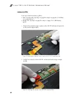
Page 68: ...Lenovo TAB 2 A10 70 Hardware Maintenance Manual 62 Figure 11 5 The removed side key FPC ...

Page 69: ...e 40 to Step 4 on page 41 in 1050 LCD FPC 1 Peel off the conductive fabric tape on the main board as shown in the figure below Figure 12 1 Peeling off the conductive fabric tape on the main board Important notices for handling PCB When handling PCB bear the following in mind Be careful not to drop the PCB onto a bench top that has a hard surface such as surface made of metal wood or composite mate...

Page 70: ...n board at the position as shown in the figure below LTE version only Figure 12 2 Positions for disconnecting the antenna cable main board side LTE version only 3 Remove the conductive fabric tape on the side key FPC as shown in the figure below Figure 12 3 Removing the conductive fabric tape on the side key FPC ...

Page 71: ...rom the front module of the tablet using a pair of tweezers Figure 12 4 Detaching the side key FPC 5 Unlock the connector of the TP FPC on the main board using a guitar pick as shown in the figure below Figure 12 5 Unlocking the connector of the TP FPC ...

Page 72: ...ctor using a pair of tweezers as shown in the figure below Figure 12 6 Pulling out the TP FPC 7 Remove screws at the positions as shown in the figure below Figure 12 7 The screws on the main board and speakers Part No Screw quantity Color Torque Phillips flat head screw M1 4 x 3 5 11 Black N A a a ...

Page 73: ...rom the front module of the tablet as shown in the figure below Figure 12 8 Removing the main board assembly from the front module of the tablet Figure 12 9 The removed main board assembly with left and right speaker microphone vibrator motor and side key FPC ...

Page 74: ...Lenovo TAB 2 A10 70 Hardware Maintenance Manual 68 Front and side view Front camera Audio Jack Power key Volume key Micro USB port Locations ...

Page 75: ...Lenovo TAB 2 A10 70 69 Rear view Left speaker Rear camera Right speaker Micro SD card slot SIM card slot LTE version only ...

Page 76: ... This section presents the following service parts Overall on page 70 Screws on page 74 Overall Parts list Note The listed technical data is applicable to both versions of the product i e the WiFi version and the LTE version unless otherwise specified ...

Page 77: ...Lenovo TAB 2 A10 70 71 ...

Page 78: ...rsion 5F78C02027 N 6 Lenovo TAB 2 A10 70 rear camera SC29A6N0A9 SC29A6N0AA N 7 Lenovo TAB 2 A10 70 right speaker WiFi version 5SB8C01468 LTE version 5SB8C02028 N 8 Lenovo TAB 2 A10 70 microphone 5M48C01463 N 9 Lenovo TAB 2 A10 70 antenna PCB LTE version only 5R28C02032 N 10 Lenovo TAB 2 A10 70 vibrator motor 5M78C01464 N 11 Lenovo TAB 2 A10 70 antenna cable 5C18C02033 N 12 Lenovo TAB 2 A10 70 micr...

Page 79: ...Lenovo TAB 2 A10 70 73 17 Lenovo TAB 2 A10 70 battery pack SB18C00020 SB18C00021 N ...

Page 80: ...Lenovo TAB 2 A10 70 Hardware Maintenance Manual 74 Screws Table 2 Parts list Screw FRU P N CRU ID Phillips cross head screw M1 4 3 5 5M89A462AV N Phillips cross head screw M1 4 3 0 5M89A33180 N ...

Page 81: ... information could include technical inaccuracies or typographical errors Changes are periodically made to the information herein these changes will be incorporated in new editions of the publication Lenovo may make improvements and or changes in the product s and or the program s described in this publication at any time without notice The products described in this document are not intended for ...

Page 82: ...s and there is no guarantee that these measurements will be the same on generally available systems Furthermore some measurements may have been estimated through extrapolation Actual results may vary Users of this document should verify the applicable data for their specific environment Lenovo and the Lenovo logo are trademarks of Lenovo in the United States or other countries or both Other compan...

Reviews: