• Locate the documentation that comes with the drive and follow those instructions in addition to the
instructions in this chapter.
• You can install up to two hot-swap SATA 2.5-inch drives for each node.
• The electromagnetic interference (EMI) integrity and cooling of the solution are protected by having all
bays and PCI and PCI Express slots covered or occupied. When you install a drive, PCI, or PCI Express
adapter, save the EMC shield and filler panel from the bay or PCI or PCI Express adapter slot cover in the
event that you later remove the device.
• For a complete list of supported optional devices for the node, see theLenovo ServerProven website.
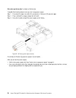
Complete the following steps to install a drive:
Note:
If you have only one drive, you must install it in the bay 0 (upper-left).
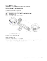
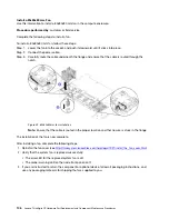
Step 1. Ensure that the tray handle is in the open (unlocked) position.
Step 2. Align the drive with the guide rails in the bay.
Step 3. Gently push the drive into the bay until the drive stops.
Step 4. Rotate the tray handle to the closed (locked) position until you hear a click.
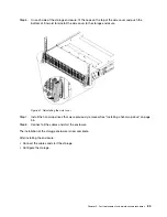
Figure 42. Drive installation
Step 5. Check the drive status LED to verify that the drive is operating correctly.
• If the yellow drive status LED is lit continuously, that drive is faulty and must be replaced.
• If the green drive activity LED is flashing, the drive is being accessed.
Step 6. Repeat steps Step 1 1 on page 93 to Step 5 5 on page 93 if installing multiple drives.
The installation of a hot-swap drive is now complete.
After you install all drives:
• If the node is configured for RAID 1 operation, you may need to re-configure your disk arrays after you
install drives. Software RAID is used in the solution.
• If you are instructed to return the component or optional device, follow all packaging instructions, and use
any packaging materials for shipping that are supplied to you.
Part replacement and maintenance procedures
93
Summary of Contents for ThinkAgile CP
Page 4: ...ii Lenovo ThinkAgile CP Hardware Part Replacement and Component Maintenance Procedures ...
Page 6: ...iv Lenovo ThinkAgile CP Hardware Part Replacement and Component Maintenance Procedures ...
Page 8: ...vi Lenovo ThinkAgile CP Hardware Part Replacement and Component Maintenance Procedures ...
Page 30: ...22 Lenovo ThinkAgile CP Hardware Part Replacement and Component Maintenance Procedures ...
Page 33: ...Chapter 4 Managing Support Mode 25 ...
Page 80: ...72 Lenovo ThinkAgile CP Hardware Part Replacement and Component Maintenance Procedures ...
Page 158: ...150 Lenovo ThinkAgile CP Hardware Part Replacement and Component Maintenance Procedures ...
Page 160: ...152 Lenovo ThinkAgile CP Hardware Part Replacement and Component Maintenance Procedures ...
Page 161: ......
Page 162: ......


