background image

User Guide for 
ThinkAgile HX1521-R Node 
ThinkAgile HX3521-G Node 
ThinkAgile HX5521 Node 
ThinkAgile HX5521-C Node 
ThinkAgile HX7521 Node

Machine Types: 

7Y90, 7Z05

Summary of Contents for ThinkAgile HX1521-R

Page 1: ...User Guide for ThinkAgile HX1521 R Node ThinkAgile HX3521 G Node ThinkAgile HX5521 Node ThinkAgile HX5521 C Node ThinkAgile HX7521 Node Machine Types 7Y90 7Z05 ...

Page 2: ...n addition be sure that you are familiar with the terms and conditions of the Lenovo warranty for your server which can be found at https datacentersupport lenovo com us zh warrantylookup First Edition July 2018 Copyright Lenovo 2018 LIMITED AND RESTRICTED RIGHTS NOTICE If data or software is delivered pursuant to a General Services Administration GSA contract use reproduction or disclosure is sub...

Page 3: ...VMware vCenter 39 Chapter 8 Hardware replacement procedures 41 Installation Guidelines 41 System reliability guidelines 42 Working inside the server with the power on 43 Handling static sensitive devices 43 Hot swap drive replacement 45 Remove a hot swap drive 45 Install a hot swap drive 47 Hot swap power supply replacement 50 Remove a hot swap power supply 50 Install a hot swap power supply 55 Sy...

Page 4: ...ii User Guide forThinkAgile HX1521 R Node ThinkAgile HX3521 G NodeThinkAgile HX5521 NodeThinkAgile HX5521 C NodeThinkAgile HX7521 Node ...

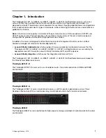
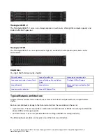
Page 5: ...anagement solution for Nutanix deployments Lenovo XClarity Administrator which provides firmware compliance functionality to ensure that the ThinkAgile HX 1521 R HX3521 G HX5521 HX5521 C HX7521 Certified Node servers are running the appropriate level of firmware for Lenovo XClarity Controller UEFI and PCIe devices Lenovo XClarity Integrator which eases the integration into Nutanix Prism The ThinkA...

Page 6: ...and Firmware Updates Best Practices Lenovo security advisories Lenovo HX Support Plan Typical Nutanix architecture A typical Nutanix architecture includes three or more servers that are implemented as a single Nutanix cluster Each server contributes storage to the Nutanix cluster from the local disks on the server Hybrid Cluster The server provides a combination of solid state disks SSDs for cachi...

Page 7: ...Switch For more information about the Lenovo ThinkSystem NE1032 RackSwitch see the following Web site https lenovopress com lp0605 lenovo thinksystem ne1032 rackswitch Understanding appliances and certified nodes When it comes to hyperconverged deployments Lenovo offers customers flexibility so that they can choose the model that best suits their business needs The ThinkAgile HX Series appliance a...

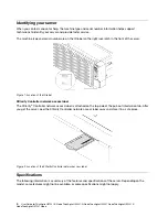
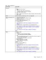
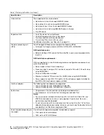
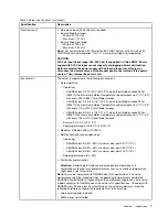
Page 8: ...twork access label is attached on the top side of the pull out information tab After you get the server peel the XClarity Controller network access label away and store it in a safe place Figure 2 Location of the XClarity Controller network access label Specifications The following information is a summary of the features and specifications of the server Depending on the model some features might ...

Page 9: ...e hx5520 hx5520 c appliances https lenovopress com lp0726 lenovo thinkagile hx1320 hx1520 r appliances ThinkAgile HX7521 https lenovopress com lp0730 lenovo thinkagile hx7520 appliance Note DIMM Minimum 8 GB Maximum 768 GB using registered DIMMs RDIMMs 1 5 TB using load reduced DIMMs LRDIMMs Type PC4 21300 DDR4 2666 operating speed depends on processor model and UEFI Operating Mode selection Singl...

Page 10: ...or equal to 150 watts 125 watts when using NVIDIA M60 Drive no NVMe drives installed Memory Limited to 1TB maximum 16 x AUNE when using the NVIDIA M60 Power supply for one GPU 1100 watt or 1600 watt power supplies installed for two GPUs 1600 watt power supplies installed Host bus adapters The following host bus adapters are supported Lenovo ThinkSystem 430 8i SAS SATA 12Gb HBA Lenovo ThinkSystem 4...

Page 11: ...ature value decreases by 1 C 1 8 F with every 175 m 574 ft of altitude increase ASHRAE class A4 5 45 C 41 113 F when the altitude exceeds 900 m 2953 ft the maximum ambient temperature value decreases by 1 C 1 8 F with every 125 m 410 ft of altitude increase Server off 5 45 C 41 113 F Shipping or storage 40 60 C 40 140 F Maximum altitude 3050 m 10 000 ft Relative humidity non condensing Operating A...

Page 12: ...ettings such as local storage I O adapters boot settings firmware ports and Lenovo XClarity Controller and UEFI settings are saved as a server pattern that can be applied to one or more managed servers When the server patterns are updated the changes are automatically deployed to the applied servers Firmware compliance and updates Firmware management is simplified by assigning firmware compliance ...

Page 13: ...ml Lenovo XClarity Integrator Lenovo also provides the following integrators that you can use to manage Lenovo servers from higher level management tools Lenovo XClarity Integrator for VMware vCenter Lenovo XClarity Integrator Microsoft System Center For more information about Lenovo XClarity Integrator see https www3 lenovo com us en data center software systems management xclarity integrators Ch...

Page 14: ...10 User Guide forThinkAgile HX1521 R Node ThinkAgile HX3521 G NodeThinkAgile HX5521 NodeThinkAgile HX5521 C NodeThinkAgile HX7521 Node ...

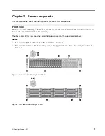
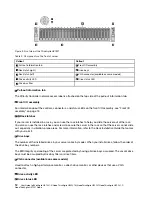
Page 15: ...ve LEDs and front I O assembly The illustrations in this topic show the server front views based on the supported drive bays Notes Your server might look different from the illustrations in this topic The chassis for sixteen 2 5 inch drive bays cannot be upgraded to the chassis for twenty four 2 5 inch drive bays Figure 3 Front view of the ThinkAgile HX3521 G Figure 4 Front view of the ThinkAgile ...

Page 16: ...out of the rack You also can use the rack latches and screws to secure the server in the rack so that the server cannot slide out especially in vibration prone areas For more information refer to the Rack Installation Guide that comes with your rail kit 4 Drive bays The number of the installed drives in your server varies by model When you install drives follow the order of the drive bay numbers T...

Page 17: ...e bay filler is used to cover vacant drive bays Front I O assembly The front I O assembly of the server provides controls connectors and LEDs The front I O assembly varies by model The following illustrations show the controls connectors and LEDs on the front I O assembly of the server To locate the front I O assembly see Front view on page 11 Figure 6 Front I O assembly Table 3 Components on the ...

Page 18: ...ption Solid on Green The server is on and running Slow blinking about one flash per second Green The server is off and is ready to be powered on standby state Fast blinking about four flashes per second Green The server is off but the XClarity Controller is initializing and the server is not ready to be powered on Off None There is no ac power applied to the server 4 Network activity LED The netwo...

Page 19: ...ature threshold The voltage of the server reached the non critical voltage threshold A fan has been detected to be running at low speed A hot swap fan has been removed The power supply has a critical error The power supply is not connected to the power Check the event log to determine the exact cause of the error Off None The server is off or the server is on and is working correctly None Rear vie...

Page 20: ...ch a device that requires a USB 2 0 or 3 0 connection such as a keyboard a mouse or a USB storage device 5 NMI button Press this button to force a nonmaskable interrupt NMI to the processor By this way you can blue screen the server and take a memory dump You might have to use a pen or the end of a straightened paper clip to press the button 6 Power supply 1 7 Power supply 2 available on some mode...

Page 21: ...Not available Slot 3 PCIe x16 x8 x4 x1 full height half length Type 4 Slot 1 PCIe x16 x8 x4 x1 full height half length Slot 2 Not available Slot 3 ML2 x16 x16 x8 x4 x1 full height half length PCIe slot 4 on the system board PCIe x8 x8 x1 low profile PCIe slots 5 and 6 on riser 2 Slot 5 PCIe x16 x16 x8 x4 x1 full height half length Slot 6 PCIe x16 x16 x8 x4 x1 full height half length 14 Rear 3 5 in...

Page 22: ... the server among other servers 2 3 Ethernet status LEDs The XClarity Controller network connector has two status LEDs Ethernet status LED Color Status Description 2 Ethernet link LED Green On Network link is established None Off Network link is disconnected 3 Ethernet activity LED Green Blinking Network link is connected and active None Off The server is disconnected from a LAN 4 System error LED...

Page 23: ...e other one delivers entire load When the power load increases the standby power supply will switch to active state to provide sufficient power to the server To disable zero output mode start the Setup utility go to System Settings Power Zero Output and select Disable If you disable zero output mode both power supplies will be in the active state Off The server is powered off or the power supply i...

Page 24: ...tor 8 XCC ROM programming connector 9 Front USB connector 10 GPU power connector 2 11 Operator information panel connector 12 TCM1 TPM2 connector for China only 13 Front VGA connector 14 DIMM slots 24 15 Backplane power connector 3 16 System fan 1 connector 17 Processor 1 socket 18 System fan 2 connector 19 System fan 3 connector 20 Backplane power connector 2 21 System fan 4 connector 22 Processo...

Page 25: ...ATA PCIe slot 8 Notes 1 Trusted Cryptography Module 2 Trusted Platform Module System board LEDs The illustration in this section shows the LEDs on the system board Figure 10 System board LEDs Table 7 LEDs on the system board Callout Callout 1 System power LED 2 System ID LED 3 System error LED 4 DIMM error LEDs 24 5 Fan 1 error LED 6 Fan 2 error LED 7 Fan 3 error LED 8 Fan 4 error LED 9 Fan 5 erro...

Page 26: ...f the system ID LEDs to assist in visually locating the server among other servers 3 System error LED When this yellow LED is lit one or more LEDs elsewhere in the server might also be lit to direct you to the source of the error For more information see Front I O assembly on page 13 4 DIMM error LEDs When a DIMM error LED is lit it indicates that the corresponding DIMM has failed 5 6 7 8 9 10 Fan...

Page 27: ... com us en products solutions and software thinkagile hx hx3520 g 7x84 parts ThinkAgile HX5521 https datacentersupport lenovo com us en products solutions and software thinkagile hx hx5520 7x84 parts ThinkAgile HX7521 https datacentersupport lenovo com us en products solutions and software thinkagile hx hx7520 7x84 parts Note Depending on the model your server might look slightly different from th...

Page 28: ...urself or request Lenovo to install it at no additional charge under the type of warranty service that is designated for your server Field replaceable unit FRU FRUs must be installed only by trained service technicians Consumable and Structural parts Purchase and replacement of consumable and structural parts is your responsibility If Lenovo acquires or installs a structural component at your requ...

Page 29: ... lenovo com us en products solutions and software thinkagile hx hx7520 7x84 parts 1 Top cover 2 RAID adapter 3 LOM adapter air baffle 4 LOM adapter 5 DIMM 6 Heat sink 7 Processor 8 TCM TPM adapter for China only 9 System board 10 Fan 11 Fan cage 12 RAID super capacitor module 13 Standard air baffle 14 Serial port module 15 Backplane eight 2 5 inch hot swap drives 16 Backplane twelve 3 5 inch hot s...

Page 30: ...nch drive bays 26 Filler 3 5 inch drive 27 Storage drive 3 5 inch hot swap 28 Filler 2 5 inch drive 29 Storage drive 2 5 inch hot swap 30 Large size air baffle 31 Riser 2 bracket 32 Riser card 33 Riser 1 bracket 34 PCIe adapter 35 Rear hot swap drive assembly 36 Power supply 37 M 2 drive 38 M 2 backplane 26 User Guide forThinkAgile HX1521 R Node ThinkAgile HX3521 G NodeThinkAgile HX5521 NodeThinkA...

Page 31: ...UL and certified by the Canadian Standards Association CSA For units intended to be operated at 115 volts Use a UL listed and CSA certified cord set consisting of a minimum 18 AWG Type SVT or SJT three conductor cord a maximum of 15 feet in length and a parallel blade grounding type attachment plug rated 15 amperes 125 volts For units intended to be operated at 230 volts U S use Use a UL listed an...

Page 32: ...28 User Guide forThinkAgile HX1521 R Node ThinkAgile HX3521 G NodeThinkAgile HX5521 NodeThinkAgile HX5521 C NodeThinkAgile HX7521 Node ...

Page 33: ...0RD Default User ID root Default Password Virtual Machines VMs IPV4 Host name User ID Password vCenter Server for ESXi only XClarity Adminis trator Infrastructure Domain DNS NTP Default Gateway Virtual Network Physical Adapters VMkernel Adapter vSwitch 0 vSwitch 1 VLAN Name VLAN ID VLAN Portgroup Assigned vSwitch VMKernel Adapter Services vMotion Provision ing FT Logging Manage ment vSphere Replic...

Page 34: ...30 User Guide forThinkAgile HX1521 R Node ThinkAgile HX3521 G NodeThinkAgile HX5521 NodeThinkAgile HX5521 C NodeThinkAgile HX7521 Node ...

Page 35: ... cabinet by using the rail kit shipped with the server See the Rack Installation Guide that comes with the rail kit b Connect the Ethernet cables and power cords to the server See Rear view on page 15 to locate the connectors See Cable the server on page 32 for cabling best practices c Power on the server See Power on the server on page 33 3 Follow the Nutanix Field Installation Guide to get the a...

Page 36: ...ource to the data network and to storage In addition you will need to connect the server to the management network Connect to power Connect the server to power Connect to the network Connect the server to the network Typically Ports 1 and 2 on the server are connected to the data network One of the ports on the network is connected to the management network if there is a separate data and manageme...

Page 37: ...onnection for the Lenovo XClarity Controller Before you can access the Lenovo XClarity Controller over your network you need to specify how Lenovo XClarity Controller will connect to the network Depending on how the network connection is implemented you might need to specify a static IP address as well The following methods are available to set the network connection for the Lenovo XClarity Contro...

Page 38: ...novofiles com help index jsp topic 2Fcom lenovo lxca doc 2Flxca_usemobileapp html Important The Lenovo XClarity Controller is set initially with a user name of USERID and password of PASSW0RD with a zero not the letter O This default user setting has Supervisor access Change this user name and password during your initial configuration for enhanced security Complete the following steps to connect ...

Page 39: ... met the following conditions All ThinkAgile HX Series servers must be connected to a network that is reachable from the host where the Foundation tool is running Note This includes both the Lenovo XClarity Controller connections as well as the data connections 10Gb 25Gb etc All ThinkAgile HX Series servers must be connected to power All ThinkAgile HX Series servers are updated to the current best...

Page 40: ...36 User Guide forThinkAgile HX1521 R Node ThinkAgile HX3521 G NodeThinkAgile HX5521 NodeThinkAgile HX5521 C NodeThinkAgile HX7521 Node ...

Page 41: ...y Deploying Lenovo XClarity Administrator Use this information to deploy Lenovo XClarity Administrator Before you begin make sure that you download the Lenovo XClarity Administrator from Lenovo Refer to the ThinkAgile HX Series Best Recipe to determine the correct version to be downloaded The ThinkAgile HX Series Best Recipe is available at the following location https support lenovo com us en sol...

Page 42: ...vo XClarity Administrator Web interface you can download install and manage firmware updates for managed ThinkAgile HX 1521 R HX3521 G HX5521 HX5521 C HX7521 Certified Node servers To update the firmware 1 Obtain the firmware update from the HX Best Recipe page https support lenovo com us en solutions ht505413 2 Follow these instructions to import the firmware update into the repository http sysmg...

Page 43: ...ing Web site https www3 lenovo com us en data center software systems management xclarity integrators Deploying Lenovo XClarity Integrator for VMware vCenter Use this procedure to install Lenovo XClarity Integrator for VMware vCenter Complete the following steps to deploy Lenovo XClarity Integrator Step 1 Download the Lenovo XClarity Integrator image The currently supported version of Lenovo XClar...

Page 44: ... lenovofiles com help topic com lenovo lxci_vcenter doc vcenter_install_config_lxci html Step 4 Manage the cluster by requesting access to the BMC of each of the servers in the cluster Information about requesting BMC access is available at http sysmgt lenovofiles com help topic com lenovo lxci_vcenter doc vcenter_using_vsphere_web_ client_request_imm_access html 40 User Guide forThinkAgile HX1521...

Page 45: ... Before installing components in your server read the installation guidelines Before installing optional devices read the following notices carefully Attention Prevent exposure to static electricity which might lead to system halt and loss of data by keeping static sensitive components in their static protective packages until installation and handling these devices with an electrostatic discharge...

Page 46: ...ling a riser card Blue on a component indicates touch points where you can grip to remove a component from or install it in the server open or close a latch and so on Orange on a component or an orange label on or near a component indicates that the component can be hot swapped if the server and operating system support hot swap capability which means that you can remove or install the component w...

Page 47: ...r forearms Button or roll up long sleeves before working inside the server Prevent your necktie scarf badge rope or long hair from dangling into the server Remove jewelry such as bracelets necklaces rings cuff links and wrist watches Remove items from your shirt pocket such as pens and pencils in case they fall into the server as you lean over it Avoid dropping any metallic objects such as paper c...

Page 48: ...the frame Do not touch solder joints pins or exposed circuitry Keep the device from others reach to prevent possible damages 44 User Guide forThinkAgile HX1521 R Node ThinkAgile HX3521 G NodeThinkAgile HX5521 NodeThinkAgile HX5521 C NodeThinkAgile HX7521 Node ...

Page 49: ... HDD SSD The Prism Web Client shows a disk alert The yellow status LED on the node front panel is illuminated Remove a hot swap drive Use this information to remove a hot swap drive Read the installation Guidelines on page 41 ATTENTION Static Sensitive Device Ground package before opening on page 43 Attention To ensure that there is adequate system cooling do not operate the server for more than t...

Page 50: ...ive Figure 13 Opening the drive tray handle of a 3 5 inch hot swap drive b Grasp the handle and slide the drive out of the drive bay 46 User Guide forThinkAgile HX1521 R Node ThinkAgile HX3521 G NodeThinkAgile HX5521 NodeThinkAgile HX5521 C NodeThinkAgile HX7521 Node ...

Page 51: ...swap drive on page 47 2 If you are instructed to return the old hot swap drive follow all packaging instructions and use any packaging materials that are provided Install a hot swap drive Use this information to install a hot swap drive Read the installation Guidelines on page 41 ATTENTION Static Sensitive Device Ground package before opening on page 43 Chapter 8 Hardware replacement procedures 47...

Page 52: ...removal 2 Touch the static protective package that contains the new drive to any unpainted surface on the outside of the server Then take the new drive out of the package and place it on a static protective surface To install a hot swap drive complete the following steps Step 1 Install the hot swap drive 48 User Guide forThinkAgile HX1521 R Node ThinkAgile HX3521 G NodeThinkAgile HX5521 NodeThinkA...

Page 53: ... using the procedure Completing Drive Replacement in the Nutanix Hardware Replacement Documentation Step 3 To replace a failed metadata drive use the Failed drive procedure in the Nutanix Hardware Replacement Documentation Step 4 Check the drive status LED to verify that the drive is operating correctly If the yellow drive status LED is lit continuously that drive is faulty and must be replaced If...

Page 54: ...hinkSystem 750W 230 115V Platinum Hot Swap Power Supply AVWE ThinkSystem 750W 230V Titanium Hot Swap Power Supply AVWF ThinkSystem 1100W 230V 115V Platinum Hot Swap Power Supply AVWG ThinkSystem 1600W 230V Platinum Hot Swap Power Supply A failed power supply unit is indicated by The Nutanix Prism Web console shows a power supply alert Amber warning LED on node front panel is illuminated The Lenovo...

Page 55: ...telephone and communication cables is hazardous To avoid a shock hazard Do not connect or disconnect any cables or perform installation maintenance or reconfiguration of this product during an electrical storm Connect all power cords to a properly wired and grounded electrical outlet Connect to properly wired outlets any equipment that will be attached to this product When possible use one hand on...

Page 56: ...moving the power supply with dc input please turn off server or disconnect dc power sources at the breaker panel or by turning off the power source Then remove the power cord 在直流输入状态下 若电源供应器插座不支持热插拔功能 请务必不要对设备电源线进行热插拔 此操作可能 导致设备损坏及数据丢失 因错误执行热插拔导致的设备故障或损坏 不属于保修范围 NEVER CONNECT AND DISCONNECT THE POWER SUPPLY CABLE AND EQUIPMENT WHILE YOUR EQUIPMENT IS POWERED ON WITH DC SUPPLY hot plugging Otherwis...

Page 57: ... serial cables before you open the device covers unless you are instructed otherwise in the installation and configuration procedures Connect and disconnect cables as described in the following table when you install move or open covers on this product or attached devices To Connect To Disconnect 1 Turn OFF all power sources and equipment that is to be attached to this product 2 Attach signal cabl...

Page 58: ...the way to gain access to the power supply Step 2 Disconnect the power cord from the hot swap power supply Note If you are replacing two power supplies do the power supply replacement one by one to ensure that the power supply to the server is not interrupted Do not disconnect the power cord from the secondly replaced power supply until the power output LED for the firstly replaced power supply is...

Page 59: ... To ensure proper cooling during normal server operation both of the power supply bays must be occupied This means that each bay must have a power supply installed or one has a power supply installed and the other has a power supply filler installed 2 If you are instructed to return the old hot swap power supply follow all packaging instructions and use any packaging materials that are provided In...

Page 60: ... the power supply Figure 23 Hot swap power supply label on the cover S035 CAUTION Never remove the cover on a power supply or any part that has this label attached Hazardous voltage current and energy levels are present inside any component that has this label attached There are no serviceable parts inside these components If you suspect a problem with one of these parts contact a service technici...

Page 61: ...First attach all cables to devices 3 Attach signal cables to connectors 4 Attach power cords to outlet 5 Turn device ON 1 Turn everything OFF 2 First remove power cords from outlet 3 Remove signal cables from connectors 4 Remove all cables from devices The following tips describe the information that you must consider when you install a power supply with dc input CAUTION 240 V dc input input range...

Page 62: ...o not connect or disconnect any cables or perform installation maintenance or reconfiguration of this product during an electrical storm Connect all power cords to a properly wired and grounded power source Connect to properly wired power sources any equipment that will be attached to this product When possible use one hand only to connect or disconnect signal cables Never turn on any equipment wh...

Page 63: ...his product For ac systems remove all power cords from the chassis power receptacles or interrupt power at the ac power distribution unit For dc systems disconnect dc power sources at the breaker panel or by turning off the power source Then remove the dc cables 2 Remove the signal cables from the connectors 3 Remove all cables from the devices Before installing a hot swap power supply touch the s...

Page 64: ... the following Figure 24 CMA adjustment a Press down the stop bracket 1 and rotate it to the open position b Rotate the CMA out of the way to gain access to the power supply bay Step 2 If there is a power supply filler installed remove it Figure 25 Hot swap power supply filler removal 60 User Guide forThinkAgile HX1521 R Node ThinkAgile HX3521 G NodeThinkAgile HX5521 NodeThinkAgile HX5521 C NodeTh...

Page 65: ...ly is illuminated No errors are shown in the Lenovo XClarity Controller No errors are shown in the Lenovo XClarity Administrator No errors are shown in the Lenovo XClarity Integrator System fan replacement Use this information to remove and install a system fan Failed or failing system fans can cause overheat and shutdown of the system Replace a failed system fan as soon as possible A failed chass...

Page 66: ...oltages with hazardous energy might cause heating when shorted with metal which might result in spattered metal burns or both S017 CAUTION Hazardous moving fan blades nearby Attention When removing a system fan without powering off the server do not touch the system fan cage Before removing a system fan 1 Remove the ThinkAgile HX 1521 R HX3521 G HX5521 HX5521 C HX7521 Certified Node server from th...

Page 67: ... the fan error LEDs from the top of the system fans To remove a system fan complete the following steps Figure 28 System fan removal Step 1 Grasp the top of the system fan with your fingers Step 2 Lift the system fan out of the server Chapter 8 Hardware replacement procedures 63 ...

Page 68: ...nd package before opening on page 43 S033 CAUTION Hazardous energy present Voltages with hazardous energy might cause heating when shorted with metal which might result in spattered metal burns or both S017 CAUTION Hazardous moving fan blades nearby Attention When installing a system fan without powering off the server do not touch the system fan cage To install a system fan complete the following...

Page 69: ...rror is shown in the Nutanix Prism Web console The error LED for the replaced system fan is off Amber warning LED on node front panel is off No error is shown in the Lenovo XClarity Controller Web interface No error is shown in the Lenovo XClarity Administrator Web console No error is shown in the Lenovo XClarity Integrator console HBA replacement Use this information to remove and install the HBA...

Page 70: ...ve the HBA Use this information to remove the HBA from the RAID adapter slot on the system board Read the installation Guidelines on page 41 Power off the server for this task on page 33 ATTENTION Static Sensitive Device Ground package before opening on page 43 Before removing the HBA 1 Place the node in maintenance mode by following the procedure Enter Maintenance Mode in the Nutanix Hardware Rep...

Page 71: ...Power off the server for this task on page 33 ATTENTION Static Sensitive Device Ground package before opening on page 43 Ensure that you follow the installation order if you install more than one HBA The RAID adapter slot on the system board The PCIe slot 4 on the system board if the serial port module is not installed A PCIe slot on the riser card Before installing the RAID adapter 1 Touch the st...

Page 72: ...LSI Logic Symbios Logic SAS3408 Fusion MPT Tri Mode I O Controller Chip IOC rev 01 If the LSI HBA card is not present ensure the card is properly connected If the card is still not detected contact Lenovo Support If the system fails to boot from the boot drive after replacing the HBA verify the option ROM is turned off for the HBA adapter 6 Exit maintenance mode LOM adapter replacement Use this in...

Page 73: ... the LOM adapter 1 ThinkAgile HX 1521 R HX3521 G HX5521 HX5521 C HX7521 Certified Node appliances can contain zero or one LOM NIC with two or four ports as well as up to two PCIe NICs For nodes with multiple NICs verify which has failed Identify the failed NIC by either checking in the XCC or checking the indicator lights on the network ports 2 Place the node in maintenance mode by following the p...

Page 74: ...e LOM adapter 1 If the server comes with a LOM adapter slot bracket remove it with a tool first Store the bracket in case that you later remove the LOM adapter and need the bracket to cover the place CAUTION Use a tool to remove the LOM adapter slot bracket to avoid injury 2 Touch the static protective package that contains the new LOM adapter to any unpainted surface on the outside of the server ...

Page 75: ...part of a cluster If one network interface is available the failure of the other network interfaces does not cause service interruption A failed NIC is indicated by No LED is illuminated for the network interface Guest VM performance degrades Guest VMs the vSphere Web console and nCLI are unavailable VM migration fails with an error message such as The migration was cancelled because the amount of...

Page 76: ...nance Mode in the Nutanix Hardware Replacement Documentation 3 Power off the node and if the cable management arm is not in place disconnect all the cables 4 Remove the appliance from the rack 5 Remove the top cover 6 Remove the riser assembly and lay it upside down on a flat clean and static protective surface To remove a PCIe adapter from the riser assembly complete the following steps Step 1 Pr...

Page 77: ...kaging materials that are provided Install a PCIe adapter on the riser assembly Use the following information to install a PCIe adapter on the riser assembly Read the installation Guidelines on page 41 Power off the server for this task on page 33 ATTENTION Static Sensitive Device Ground package before opening on page 43 Before installing a PCIe adapter on the riser assembly 1 Touch the static pro...

Page 78: ...bracket also is secured Figure 36 PCIe adapter installation Note Carefully handle the PCIe adapter by its edges Step 2 Pivot the PCIe adapter retention latch to the closed position Figure 37 Closing the PCIe adapter retention latch 74 User Guide forThinkAgile HX1521 R Node ThinkAgile HX3521 G NodeThinkAgile HX5521 NodeThinkAgile HX5521 C NodeThinkAgile HX7521 Node ...

Page 79: ...DIMM ThinkSystem 32GB TruDDR4 2666 MHz 2Rx4 1 2V RDIMM ThinkSystem 64GB TruDDR4 2666 MHz 4Rx4 1 2V LRDIMM Indications of a failed DIMM are The Nutanix Prism Web console shows a memory error A post error on boot An error in the Lenovo XClarity Controller interface Not all memory is detected For example the appliance should have 256 GB per node and the host only shows 240 GB Remove a DIMM Use this i...

Page 80: ...ntation 3 Power off the node and if the cable management arm is not in place disconnect all the cables 4 Remove the appliance from the rack 5 Remove the top cover 6 Remove the air baffle To remove a DIMM complete the following steps Figure 38 DIMM removal Step 1 Open the retaining clips on each end of the DIMM slot Attention To avoid breaking the retaining clips or damaging the DIMM slots handle t...

Page 81: ...MM installed in each of the 24 DIMM slots 1 5 TB using LRDIMMs two processors installed and one 64 GB LRDIMM installed in each of the 24 DIMM slots 3 TB using 3DS RDIMMs two processors installed and one 128 GB 3DS RDIMM installed in each of the 24 DIMM slots For a list of supported DIMM options see http static lenovo com us en serverproven index shtml Before installing a DIMM ensure that all DIMMs...

Page 82: ... the ten DIMMs have the same Lenovo part number move the DIMM to be installed in slot 6 to slot 12 Table 11 Independent mode with one processor Total Processor 1 Total DIMMs 12 11 10 9 8 7 6 5 4 3 2 1 DIMMs 1 5 1 2 8 5 2 3 8 5 3 3 4 10 8 5 3 4 5 10 8 5 3 1 5 6 12 10 8 5 3 1 6 7 12 10 8 6 5 4 3 7 8 10 9 8 7 6 5 4 3 8 9 12 10 8 6 5 4 3 2 1 9 10 10 9 8 7 6 5 4 3 2 1 10 11 12 10 9 8 7 6 5 4 3 2 1 11 1...

Page 83: ...8 7 6 5 4 3 15 16 22 21 20 19 18 17 16 15 10 9 8 7 6 5 4 3 16 17 22 21 20 19 18 17 16 15 12 10 8 6 5 4 3 2 1 17 18 24 22 20 18 17 16 15 14 13 12 10 8 6 5 4 3 2 1 18 19 24 22 20 18 17 16 15 14 13 10 9 8 7 6 5 4 3 2 1 19 20 22 21 20 19 18 17 16 15 14 13 10 9 8 7 6 5 4 3 2 1 20 21 24 22 20 18 17 16 15 14 13 12 11 10 9 8 7 6 5 4 3 2 1 21 22 24 22 21 20 19 18 17 16 15 14 13 12 10 9 8 7 6 5 4 3 2 1 22 2...

Page 84: ...12 10 8 5 3 1 12 13 22 20 17 15 12 10 8 6 5 4 3 2 1 13 14 22 21 20 19 18 17 16 15 12 10 8 5 3 1 14 15 24 22 20 17 15 13 12 10 8 6 5 4 3 2 1 15 16 22 21 20 19 18 17 16 15 10 9 8 7 6 5 4 3 16 17 22 21 20 19 18 17 16 15 12 10 8 6 5 4 3 2 1 17 18 24 22 20 17 15 13 12 11 10 9 8 7 6 5 4 3 2 1 18 20 22 21 20 19 18 17 16 15 12 11 10 9 8 7 6 5 4 3 2 1 20 21 24 22 20 18 17 16 15 14 13 12 11 10 9 8 7 6 5 4 3...

Page 85: ... mode with two processors Total Processor 2 Processor 1 Total DIMMs 24 23 22 21 20 19 18 17 16 15 14 13 12 11 10 9 8 7 6 5 4 3 2 1 DIMMs 4 18 17 6 5 4 6 18 17 8 7 6 5 6 8 20 19 18 17 8 7 6 5 8 10 20 19 18 17 8 7 6 5 4 3 10 12 20 19 18 17 16 15 8 7 6 5 4 3 12 14 20 19 18 17 16 15 10 9 8 7 6 5 4 3 14 16 22 21 20 19 18 17 16 15 10 9 8 7 6 5 4 3 16 18 22 21 20 19 18 17 16 15 10 9 8 7 6 5 4 3 2 1 18 20...

Page 86: ...DIMM Before installing a DIMM 1 Touch the static protective package that contains the new DIMM to any unpainted surface on the outside of the server Then take the new DIMM out of the package and place it on a static protective surface 2 Locate the required DIMM slot on the system board and ensure that you observe the installation rules and sequence See DIMM installation rules on page 77 To install...

Page 87: ...e replacement An assembled M 2 backplane and M 2 drive is also known as M 2 module Lenovo support may ask that the M 2 module or M 2 backplane and M 2 drive be replaced Remove the M 2 backplane and M 2 drive Use this information to remove the M 2 backplane and M 2 drive Read the installation Guidelines on page 41 Power off the server for this task on page 33 ATTENTION Static Sensitive Device Groun...

Page 88: ...both ends and pull it straight up to remove it from the system board Figure 41 M 2 backplane removal 84 User Guide forThinkAgile HX1521 R Node ThinkAgile HX3521 G NodeThinkAgile HX5521 NodeThinkAgile HX5521 C NodeThinkAgile HX7521 Node ...

Page 89: ...e and M 2 drive on page 86 If you are instructed to return the old M 2 backplane or M 2 drive follow all of the packaging instructions and use any packaging materials that are provided Adjust the retainer on the M 2 backplane Use this information to adjust the retainer on the M 2 backplane Read the installation Guidelines on page 41 Power off the server for this task on page 33 ATTENTION Static Se...

Page 90: ...TTENTION Static Sensitive Device Ground package before opening on page 43 Before installing the M 2 backplane and M 2 drive 1 Touch the static protective package that contains the new M 2 backplane and M 2 drive to any unpainted surface on the outside of the server Then take the new M 2 backplane and M 2 drive out of the package and place them on a static protective surface 2 Adjust the retainer o...

Page 91: ...e M 2 drive down until the notch 1 catches on the lip of the retainer 2 Step 3 Slide the retainer forward toward the connector to secure the M 2 drive into place Attention When sliding the retainer forward ensure that the two nubs 3 on the retainer enter the small holes 4 on the M 2 backplane Once they enter the holes you will hear a soft click sound Figure 45 Instruction for sliding the retainer ...

Page 92: ...cover 3 Install the node back into the rack and reconnect all cables 4 Power on the node 5 Exit maintenance mode 6 Use the Lenovo XClarity Provisioning Manager to configure the RAID For more information see http sysmgt lenovofiles com help topic LXPM RAID_setup html 7 Verify that the M 2 module is replaced successfully The amber warning light on the node front panel is off The system boots success...

Page 93: ...the update and then directing the update to the target subsystem or device Out of band updates have no dependency on an operating system executing on the core CPU However most out of band operations do require the server to be in the S0 Working power state On Target update The installation or update is initiated from an Operating System executing on the server s operating system Off Target update ...

Page 94: ...ou can use the Lenovo XClarity Controller interface for a specific server Notes To perform an in band update through Windows or Linux the operating system driver must be installed and the Ethernet over USB sometimes called LAN over USB interface must be enabled Additional information about configuring Ethernet over USB is available at http sysmgt lenovofiles com help index jsp topic 2Fcom lenovo s...

Page 95: ...those endpoints and flags any endpoints that are out of compliance Specific details about updating firmware using Lenovo XClarity Administrator are available at http sysmgt lenovofiles com help index jsp topic 2Fcom lenovo lxca doc 2Fupdate_fw html Chapter 9 Updating firmware 91 ...

Page 96: ...92 User Guide forThinkAgile HX1521 R Node ThinkAgile HX3521 G NodeThinkAgile HX5521 NodeThinkAgile HX5521 C NodeThinkAgile HX7521 Node ...

Page 97: ...PM_introduction html Enable Direct Cache Access DCA To enable DCA 1 From the Lenovo XClarity Provisioning Manager click UEFI Settings System Settings Processors 2 From the DCA drop down list click Enable Set Power Performance Bias To set the power performance biasA 1 From the Lenovo XClarity Provisioning Manager click UEFI Settings System Settings Power 2 From the Power Performance Bias drop down ...

Page 98: ...ng Manager click UEFI Settings Boot Manager 2 Click Change Boot Order 3 Set the order to a CD DVD Rom b Hard Disk 0 c Network 94 User Guide forThinkAgile HX1521 R Node ThinkAgile HX3521 G NodeThinkAgile HX5521 NodeThinkAgile HX5521 C NodeThinkAgile HX7521 Node ...

Page 99: ...t more information about Lenovo products use the Lenovo Support Plan for ThinkAgile HX Details for the ThinkAgile HX Support Plan are available at the following site https datacentersupport lenovo com us en products solutions and software thinkagile hx hx1520 r 7x84 solutions ht505404 Copyright Lenovo 2018 95 ...

Page 100: ...96 User Guide forThinkAgile HX1521 R Node ThinkAgile HX3521 G NodeThinkAgile HX5521 NodeThinkAgile HX5521 C NodeThinkAgile HX7521 Node ...

Page 101: ...rademarks of Intel Corporation in the United States other countries or both Microsoft and Windows are trademarks of the Microsoft group of companies Linux is a registered trademark of Linus Torvalds All other trademarks are the property of their respective owners 2018 Lenovo Copyright Lenovo 2018 97 ...

Page 102: ...98 User Guide forThinkAgile HX1521 R Node ThinkAgile HX3521 G NodeThinkAgile HX5521 NodeThinkAgile HX5521 C NodeThinkAgile HX7521 Node ...

Page 103: ... swap power supply installing 55 removing 50 replacing 50 I ID label 4 installation guidelines 41 installation guidelines 41 installing DIMM 81 HBA 67 hot swap drive 47 hot swap power supply 55 LOM adapter 70 M 2 backplane and M 2 drive 86 system fan 64 introduction 1 4 L Lenovo XClarity Administrator 8 Lenovo XClarity Integrator 8 LOM adapter installing 70 removing 69 replacing 68 M M 2 backplane...

Page 104: ...kplane adjusting 85 S server components 11 server setup checklist 31 solid state drive replacing 45 static sensitive devices handling 43 system board components 20 system board LED 21 system error LED 13 21 system fan installing 64 removing 62 replacing 61 system ID button 13 system ID LED 13 21 system power LED 21 system reliability guidelines 42 T trademarks 97 V VGA connector 11 W warranty 4 wo...

Page 105: ......

Page 106: ......

Reviews: