


If the XClarity Controller USB connector is set to have both the USB 2.0 function and XClarity Controller
management function, you can press the system ID button for three seconds to switch between the two
functions.
6
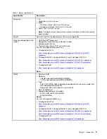
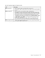
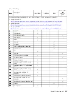
System error LED
The system error LED provides basic diagnostic functions for your server. If the system error LED is lit, one or
more LEDs elsewhere in the server might also be lit to direct you to the source of the error.
Status
Color
Description
Action
On
Yellow
An error has been detected on the server.
Causes might include but not limited to the
following errors:
• The temperature of the server reached
the non-critical temperature threshold.
• The voltage of the server reached the
non-critical voltage threshold.
• A fan has been detected to be running at
low speed.
• A hot-swap fan has been removed.
• The power supply has a critical error.
• The power supply is not connected to
the power.
Check the event log to determine the exact
cause of the error.
Off
None
The server is off or the server is on and is
working correctly.
None.
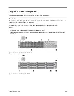
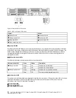
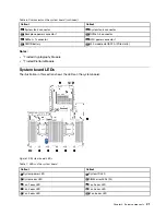
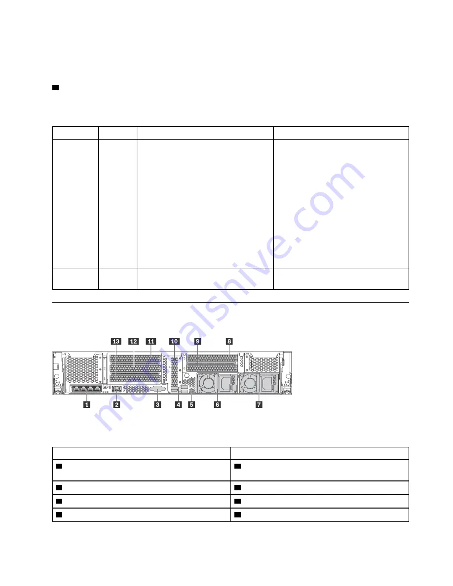
Rear view
The rear of the server provides access to several connectors and components.
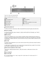
Figure 7. Rear view of the server
Table 4. Components on the rear of the server
Callout
Callout
1
Ethernet connectors on the LOM adapter (available on
some models)
2
XClarity Controller network connector
3
VGA connector
4
USB 3.0 connectors (2)
5
NMI button
6
Power supply 1
7
Power supply 2 (available on some models)
8
PCIe slot 5 (on riser 2)
.
15


