


To remove and reinstall the frame foot, do the following:
1. Remove all media from the drives and turn off all attached devices and the computer. Then, disconnect
all power cords from electrical outlets and disconnect all cables that are connected to the computer.
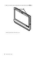
2. Place a soft, clean towel or cloth on the desk or surface. Hold the sides of your computer and gently lay
it down so that the screen is against the surface and the cover is facing up.
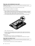
3. Remove the frame stand. See “Removing and reinstalling the frame stand” on page 36.
4. Remove the computer cover. See “Removing the computer cover” on page 36.
5. Locate the frame foot. See “Locating components” on page 12.
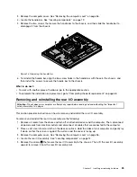
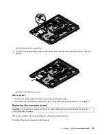
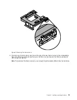
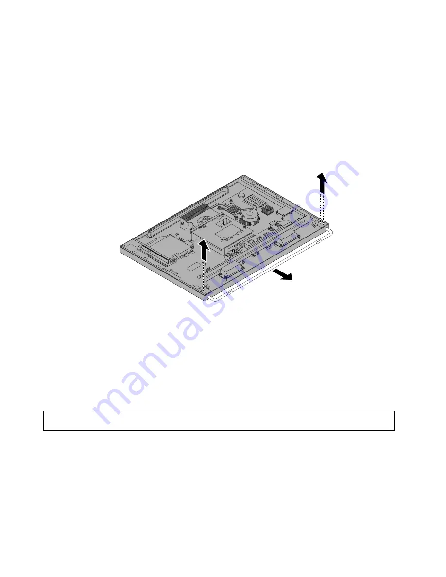
6. Remove the four screws that secure the frame foot to the chassis, and then slide the frame foot out of
the chassis.
Figure 13. Removing the frame foot
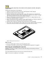
7. To reinstall the frame foot, align the four screw holes in the frame foot with those in the chassis, and then
install the screws to secure the frame foot to the chassis.
What to do next:
• To work with another piece of hardware, go to the appropriate section.
• To complete the installation or replacement, go to “Completing the parts replacement” on page 68.
Removing and reinstalling the handle bar
Attention:
Do not open your computer or attempt any repair before reading and understanding the “Important
safety information” on page v.
This section provides instructions on how to remove and reinstall the handle bar.
Note:
The handle bar is available only in models with the 20-inch display.
To remove and reinstall the handle bar, do the following:
1. Remove all media from the drives and turn off all attached devices and the computer. Then, disconnect
all power cords from electrical outlets and disconnect all cables that are connected to the computer.
2. Place a soft, clean towel or cloth on the desk or surface. Hold the sides of your computer and gently lay
it down so that the screen is against the surface and the cover is facing up.
38
ThinkCentre User Guide
Summary of Contents for ThinkCentre 3311
Page 6: ...iv ThinkCentre User Guide ...
Page 12: ...x ThinkCentre User Guide ...
Page 26: ...Figure 4 Component locations for models with the 23 inch display 14 ThinkCentre User Guide ...
Page 38: ...26 ThinkCentre User Guide ...
Page 82: ...70 ThinkCentre User Guide ...
Page 90: ...78 ThinkCentre User Guide ...
Page 120: ...108 ThinkCentre User Guide ...
Page 124: ...112 ThinkCentre User Guide ...
Page 130: ...118 ThinkCentre User Guide ...
Page 134: ...122 ThinkCentre User Guide ...
Page 136: ...124 ThinkCentre User Guide ...
Page 146: ...134 ThinkCentre User Guide ...
Page 150: ...138 ThinkCentre User Guide ...
Page 151: ......
Page 152: ......


