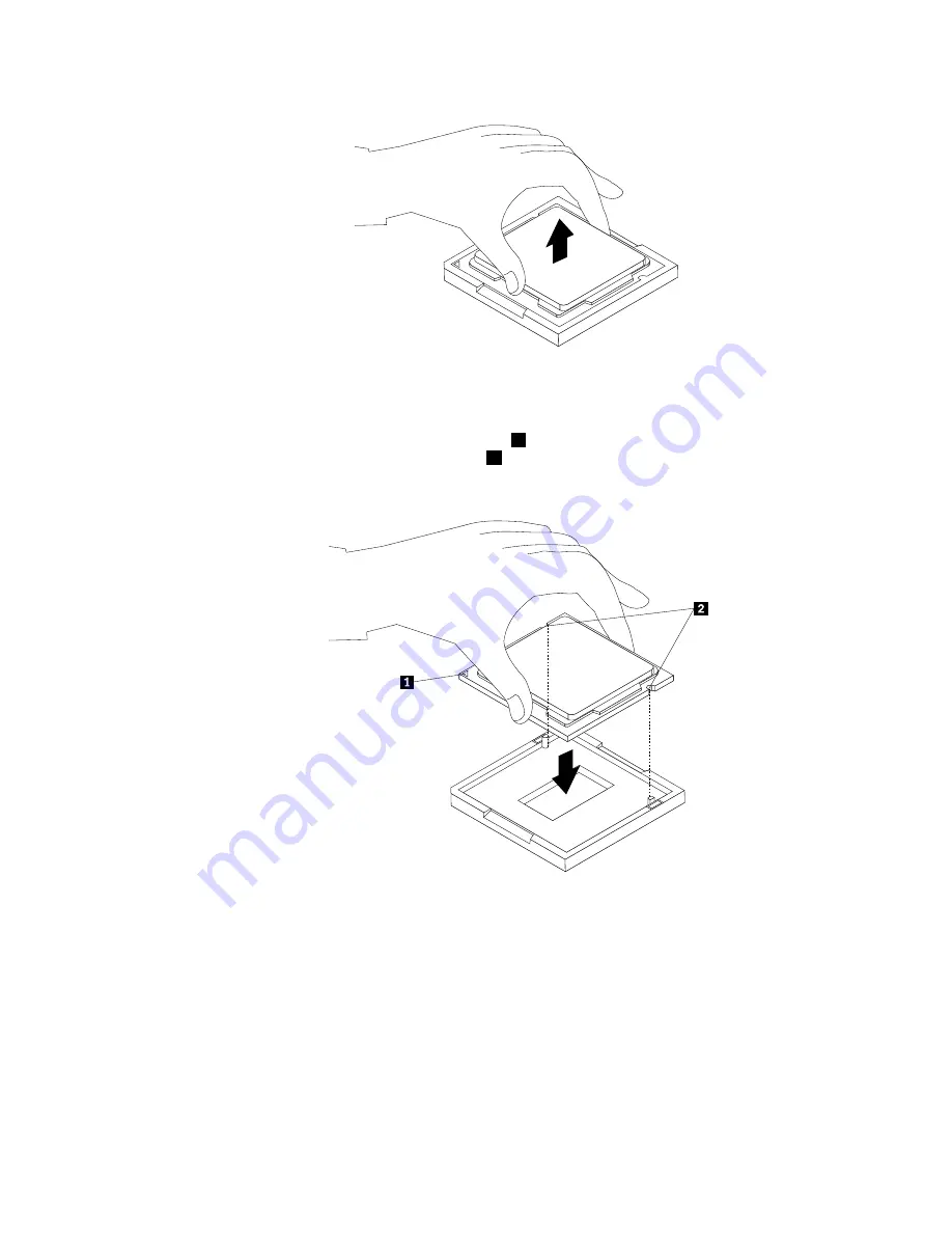
Figure 30. Removing the microprocessor
9. Make sure that the small handle is in the raised position and the microprocessor retainer is fully open.
10. Hold the new microprocessor and align the notches
2
on it with the alignment keys in the
microprocessor socket, or align the small triangle
1
on one corner of the new microprocessor with the
corresponding beveled corner of the microprocessor socket.
Figure 31. Installing the microprocessor
11. Lower the new microprocessor straight down into the microprocessor socket on the system board.
12. Close the microprocessor retainer and lock it into position with the small handle to secure the new
microprocessor in the socket.
13. Reinstall the heat sink assembly. See “Replacing the heat sink assembly” on page 91.
14. Reinstall the system board shield. See “Removing and reinstalling the system board shield” on page 88.
15. Go to “Completing the parts replacement” on page 111.
Chapter 9
.
Replacing FRUs
95
Summary of Contents for ThinkCentre 3512
Page 2: ......
Page 8: ...2 ThinkCentre Hardware Maintenance Manual ...
Page 15: ...Chapter 2 Safety information 9 ...
Page 19: ...Chapter 2 Safety information 13 ...
Page 20: ...1 2 14 ThinkCentre Hardware Maintenance Manual ...
Page 21: ...1 2 Chapter 2 Safety information 15 ...
Page 26: ...1 2 20 ThinkCentre Hardware Maintenance Manual ...
Page 27: ...1 2 Chapter 2 Safety information 21 ...
Page 30: ...24 ThinkCentre Hardware Maintenance Manual ...
Page 34: ...28 ThinkCentre Hardware Maintenance Manual ...
Page 60: ...54 ThinkCentre Hardware Maintenance Manual ...
Page 70: ...64 ThinkCentre Hardware Maintenance Manual ...
Page 75: ...Figure 3 Locating major FRUs and CRUs Chapter 8 Locations 69 ...
Page 85: ...Figure 12 Removing the frame stand Chapter 9 Replacing FRUs 79 ...
Page 127: ......
Page 128: ......


