3. Remove the computer cover. See “Removing the computer cover” on page 81.
4. Locate the memory slots on the system board. See “Locating major FRUs and CRUs” on page 68.
5. Remove the system board shield or open the system board shield window to get access to the battery.
See “Removing and reinstalling the system board shield” on page 88 or “Opening the system board
shield window” on page 97.
6. Remove any parts and disconnect any cables that might prevent your access to the memory slots.
7. Do one of the following:
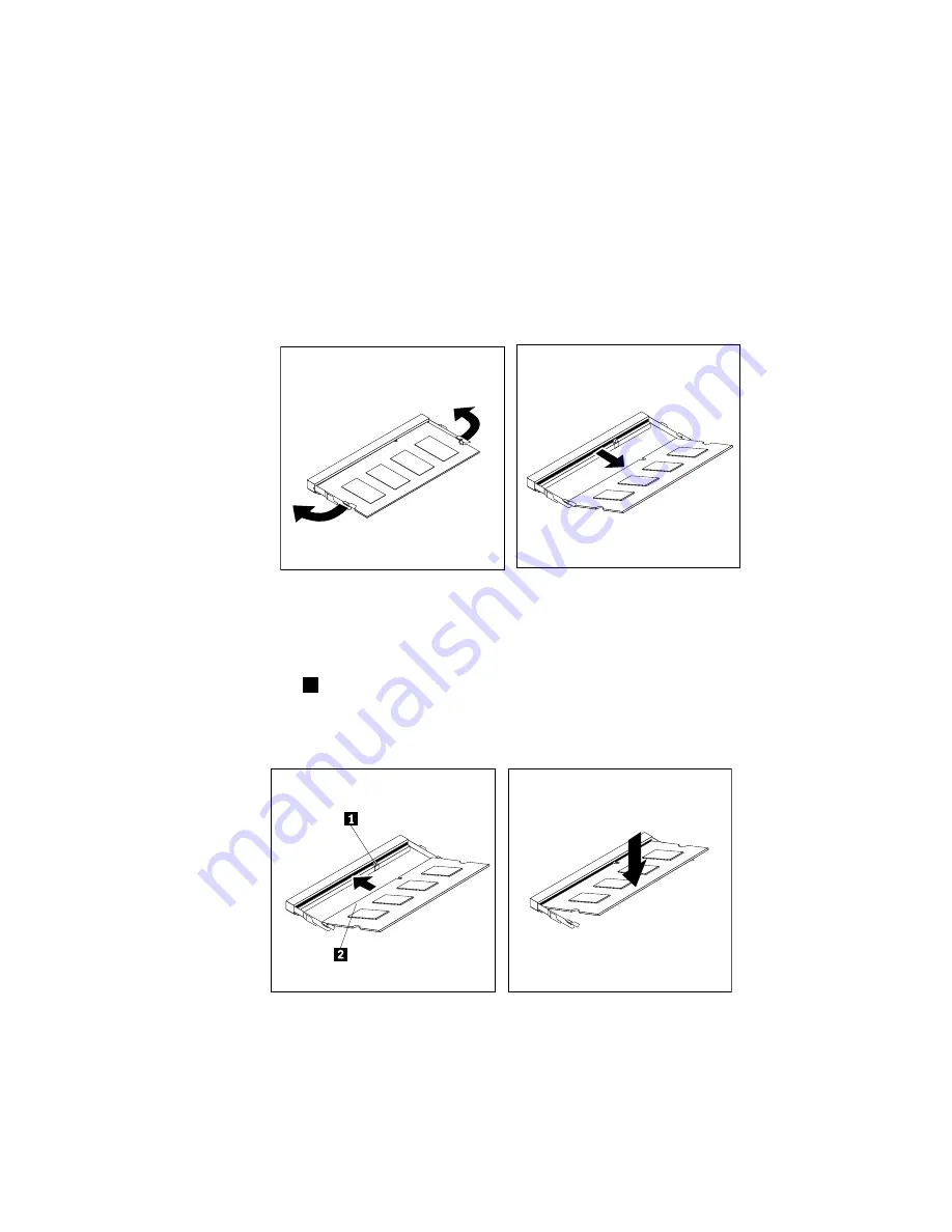
• If you are replacing a memory module, open the retaining clips and remove the old memory module
that is currently installed.
Figure 36. Removing a memory module
• If you are installing a memory module, open the retaining clips of the memory slot into which you
want to install the memory module.
8. Insert the notched end
1
of the new memory module into the slot. Press the memory module firmly
and pivot the memory module until it snaps into place. Make sure that the memory module is secured
in the slot and does not move easily.
Figure 37. Installing a memory module
9. Reinstall the system board shield or close the system board shield window. See “Removing and
reinstalling the system board shield” on page 88 or “Opening the system board shield window” on
page 97.
10. Go to “Completing the parts replacement” on page 111.
Chapter 9
.
Replacing FRUs
101
Summary of Contents for ThinkCentre 3512
Page 2: ......
Page 8: ...2 ThinkCentre Hardware Maintenance Manual ...
Page 15: ...Chapter 2 Safety information 9 ...
Page 19: ...Chapter 2 Safety information 13 ...
Page 20: ...1 2 14 ThinkCentre Hardware Maintenance Manual ...
Page 21: ...1 2 Chapter 2 Safety information 15 ...
Page 26: ...1 2 20 ThinkCentre Hardware Maintenance Manual ...
Page 27: ...1 2 Chapter 2 Safety information 21 ...
Page 30: ...24 ThinkCentre Hardware Maintenance Manual ...
Page 34: ...28 ThinkCentre Hardware Maintenance Manual ...
Page 60: ...54 ThinkCentre Hardware Maintenance Manual ...
Page 70: ...64 ThinkCentre Hardware Maintenance Manual ...
Page 75: ...Figure 3 Locating major FRUs and CRUs Chapter 8 Locations 69 ...
Page 85: ...Figure 12 Removing the frame stand Chapter 9 Replacing FRUs 79 ...
Page 127: ......
Page 128: ......


