background image

ThinkCentre
Hardware Installation and Replacement Guide

Machine Types

6137, 6234, 6258, 6303, 7174, 7220, 7346, 7354, 7357,

7360, 7483, 7627, 7630, 7638, 8910, 9964

Summary of Contents for ThinkCentre 6137

Page 1: ...ThinkCentre Hardware Installation and Replacement Guide Machine Types 6137 6234 6258 6303 7174 7220 7346 7354 7357 7360 7483 7627 7630 7638 8910 9964 ...

Page 2: ......

Page 3: ...ThinkCentre Hardware Installation and Replacement Guide ...

Page 4: ...oftware and services have been developed exclusively at private expense and are sold to governmental entities as commercial items as defined by 48 C F R 2 101 with limited and restricted rights to use reproduction and disclosure LIMITED AND RESTRICTED RIGHTS NOTICE If products data computer software or services are delivered pursuant a General Services Administration GSA contract use reproduction ...

Page 5: ...nents and drives 13 Installing a memory module 13 Installing an adapter card 15 Installing internal drives 16 Replacing the battery 20 Replacing the power supply 21 Replacing the heat sink and fan assembly 23 Replacing a hard disk drive 25 Replacing an optical drive 26 Replacing a memory module 28 Replacing an adapter card 30 Replacing the card reader 31 Replacing the keyboard 33 Replacing the mou...

Page 6: ...iv ThinkCentre Hardware Installation and Replacement Guide ...

Page 7: ...ower supply retaining screws 21 16 Power connectors on the system board 22 17 Removing the power supply 22 18 Accessing the heat sink 23 19 Removing the heat sink and fan assembly 24 20 Removing the hard disk drive 25 21 Removing the hard disk drive from the bracket 26 22 Accessing the optical drive 27 23 Removing the optical drive 27 24 Installing the optical drive 28 25 Accessing the system boar...

Page 8: ...vi ThinkCentre Hardware Installation and Replacement Guide ...

Page 9: ...afety and Warranty Guide that you received with this product for the latest safety information Reading and understanding the safety information reduces the risk of personal injury and or damage to your product If you no longer have a copy of the ThinkCentre Safety and Warranty Guide you can obtain one online from the Lenovo Support Web site at http www lenovo com support Copyright Lenovo 2008 1 ...

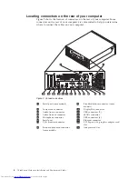
Page 10: ...2 ThinkCentre Hardware Installation and Replacement Guide ...

Page 11: ...and or replacing the following parts v Battery v Power supply v Heat sink and fan assembly v Hard disk drive v Optical drive v Memory module v Adapter card v Card reader v Keyboard v Mouse Additional information resources If you have Internet access the most up to date information for your computer is available at http www lenovo com support You can find v CRU removal and installation information ...

Page 12: ...ds and microprocessors by the edges Never touch any exposed circuitry v Prevent others from touching the parts and other computer components v Before you replace a new part touch the static protective package containing the part to a metal expansion slot cover or other unpainted metal surface on the computer for at least two seconds This reduces static electricity in the package and your body v Wh...

Page 13: ...ols and connectors on the front of your computer Figure 1 shows the location of the controls and connectors on the front of your computer Note Not all computer models have the following controls and connectors 1 USB connector 3 Headphone connector 2 Microphone connector 4 USB connector Figure 1 Controls and connectors Chapter 2 Overview 5 ...

Page 14: ... Standard mouse connector some models 2 Power cord connector 10 DisplayPort connector 3 Audio line in connector 11 USB connectors 2 4 Audio line out connector 12 eSATA connector 5 Microphone connector 13 USB connectors 4 6 Serial port 14 Ethernet connector 7 VGA monitor connector 15 PCI Express x16 graphics adapter card slot 8 Standard keyboard connector some models 16 Adapter card slot Figure 2 C...

Page 15: ...l audio device a cable is connected between the audio line out connector of the device and the audio line in connector of the computer Audio line out connector Used to send audio signals from the computer to external devices such as powered stereo speakers speakers with built in amplifiers headphones multimedia keyboards or the audio line in connector on a stereo system or other external recording...

Page 16: ...gure 3 shows the location of the various components in your computer 1 Hard disk drive 4 Internal speaker 2 Microprocessor heat sink and fan assembly 5 Memory slots 4 3 Optical drive 6 Power supply Figure 3 Component locations 8 ThinkCentre Hardware Installation and Replacement Guide ...

Page 17: ...tor 4 Internal speaker connector 14 Front audio connector 5 Cover presence Intrusion switch connector 15 SATA connectors 2 6 Microprocessor fan connector 16 System fan connector 7 Thermal sensor connector 17 Front USB connector 1 8 Microprocessor 18 Front USB connector 2 9 4 pin power connector 19 Clear CMOS Recovery jumper 10 Front panel connector 20 Power fan connector Figure 4 System board part...

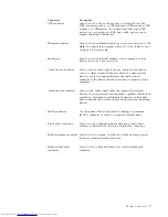
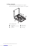
Page 18: ...10 ThinkCentre Hardware Installation and Replacement Guide ...

Page 19: ...ain a copy of the ThinkCentre Safety and Warranty Guide go to http www lenovo com support Note Use only parts provided by Lenovo Installing external options External speakers a printer or a scanner can be connected to your computer For some external options you must install additional software in addition to making the physical connection When adding an external option see Locating connectors on t...

Page 20: ...2 Unplug all power cords from electrical outlets 3 Disconnect the cables attached to the computer This includes power cords input output I O cables and any other cables that are connected to the computer See Locating controls and connectors on the front of your computer on page 5 and Locating connectors on the rear of your computer on page 6 4 Remove any locking devices such as a cable lock that s...

Page 21: ...alling a memory module Your computer has four slots for installing DDR3 DIMMs double data rate 3 dual inline memory modules that provide up to a maximum of 8 GB of system memory When installing memory modules use the following guidelines v Use 1 8 V 240 pin DDR3 SDRAM double data rate 3 synchronous dynamic random access memory v Use 1 GB or 2 GB memory modules in any combination up to a maximum of...

Page 22: ...board Push the memory module straight down into the slot until the retaining clips close What to do next v To work with another option go to the appropriate section v To complete the installation go to Chapter 4 Completing the parts replacement on page 35 Figure 7 Retaining clips Figure 8 Positioning the memory module 14 ThinkCentre Hardware Installation and Replacement Guide ...

Page 23: ...apter card from its static protective package 4 Install the adapter card 2 into the appropriate adapter card slot on the system board Note The white slot is for the PCI adapter card and the black slot is for the PCI Express x16 adapter card 5 Rotate the adapter card retainer to the closed position What to do next v To work with another option go to the appropriate section v To complete the install...

Page 24: ...vanced Technology Attachment SATA hard disk drives v SATA optical drives such as CD drives or DVD drives v Removable media drives Note These types of drives are also referred to as integrated drive electronics IDE drives Internal drives are installed in bays In this book the bays are referred to as bay 1 and bay 2 When you install an internal drive it is important to note the type and size of the ...

Page 25: ... install in each bay 1 Bay 1 Internal hard disk drive 1 8 inch Solid State Drive requires a Universal Adapter Bracket 3 5 to 1 8 inch 2 Bay 2 Maximum height 43 0 mm 1 7 inch Optical drive such as CD drive or DVD drive preinstalled in some models 3 5 inch hard disk drive requires a Universal Adapter Bracket 5 25 to 3 5 inch 5 25 inch hard disk drive You can obtain a Universal Adapter Bracket 5 25 t...

Page 26: ...cal computer retailer or by contacting the Customer Support Center 4 Slide the drive into the bay until it locks into position 5 Pivot the drive bay assembly upward to gain access to the cable connections and connect the drive signal and power cables 6 Continue at Connecting a Serial ATA drive Connecting a Serial ATA drive A serial optical drive or an additional hard disk drive can be connected to...

Page 27: ... next v To work with another option go to the appropriate section v To complete the installation go to Chapter 4 Completing the parts replacement on page 35 Figure 12 Connecting the five wire power cable and signal cable to the drive Chapter 3 Installing options and replacing hardware 19 ...

Page 28: ...place the battery 1 Open the computer cover See Opening the cover on page 12 2 Access the system board See Accessing system board components and drives on page 13 3 Locate the battery See Identifying parts on the system board on page 9 4 Remove the old battery 5 Install the new battery 6 Close the computer cover and connect the cables See Chapter 4 Completing the parts replacement on page 35 Note ...

Page 29: ...y and Warranty Guide go to http www lenovo com support To replace the power supply 1 Remove the four screws at the rear of the chassis that secure the power supply 2 Open the computer cover See Opening the cover on page 12 3 Pivot the drive bay assembly upward to gain access to the power supply 4 Locate the power supply See Locating components on page 8 Figure 15 Power supply retaining screws Chap...

Page 30: ... on page 25 6 Remove the power supply cables from the cable clips and ties 7 Slide the power supply away from the chassis and remove it from the computer 8 Install the new power supply into the chassis so that the screw holes in the power supply align with those in the chassis Figure 16 Power connectors on the system board Figure 17 Removing the power supply 22 ThinkCentre Hardware Installation an...

Page 31: ... drives and the system board 12 Go to Chapter 4 Completing the parts replacement on page 35 Replacing the heat sink and fan assembly Attention Do not open your computer or attempt any repair before reading the Important safety information in the ThinkCentre Safety and Warranty Guide that came with your computer To obtain a copy of the ThinkCentre Safety and Warranty Guide go to http www lenovo com...

Page 32: ...assembly off the system board Note It helps to remove the hard disk drive before this step See Replacing a hard disk drive on page 25 5 Place the new heat sink and fan assembly into position and lower the lever to secure the heat sink and fan assembly 6 Connect the heat sink and fan assembly cable to the microprocessor fan connector on the system board 7 Go to Chapter 4 Completing the parts replac...

Page 33: ...as when your computer was originally shipped from the factory For more information on recovering factory installed software refer to Recovering software in your ThinkCentre User Guide To replace the hard disk drive 1 Open the computer cover See Opening the cover on page 12 2 You might need to pivot the drive bay assembly upward to gain easy access to the hard disk drive 3 Locate the hard disk driv...

Page 34: ... until the two clips on the blue handle of the hard disk drive bracket snap into place 10 Go to Chapter 4 Completing the parts replacement on page 35 Replacing an optical drive Attention Do not open your computer or attempt any repair before reading the Important safety information in the ThinkCentre Safety and Warranty Guide that came with your computer To obtain a copy of the ThinkCentre Safety ...

Page 35: ...he signal and power cables from the rear of the optical drive 4 Press the optical drive lock 1 5 Slide the optical drive out the rear of the drive bay assembly Figure 22 Accessing the optical drive Figure 23 Removing the optical drive Chapter 3 Installing options and replacing hardware 27 ...

Page 36: ...e reading the Important safety information in the ThinkCentre Safety and Warranty Guide that came with your computer To obtain a copy of the ThinkCentre Safety and Warranty Guide go to http www lenovo com support This section provides instructions on how to replace a memory module Your computer can support a maximum of four memory modules 1 Open the computer cover See Opening the cover on page 12 ...

Page 37: ... and drives on page 13 3 Locate the memory slots See Identifying parts on the system board on page 9 4 Remove the memory module being replaced by opening the retaining clips as shown Figure 25 Accessing the system board Figure 26 Removing the memory module Chapter 3 Installing options and replacing hardware 29 ...

Page 38: ... an adapter card Attention Do not open your computer or attempt any repair before reading the Important safety information in the ThinkCentre Safety and Warranty Guide that came with your computer To obtain a copy of the ThinkCentre Safety and Warranty Guide go to http www lenovo com support This section provides instructions on how to replace an adapter card 1 Open the computer cover See Opening ...

Page 39: ...ant safety information in the ThinkCentre Safety and Warranty Guide that came with your computer To obtain a copy of the ThinkCentre Safety and Warranty Guide go to http www lenovo com support This section provides instructions on how to replace the card reader 1 Open the computer cover See Opening the cover on page 12 2 Pivot the drive bay assembly upward to gain access to the card reader 3 Locat...

Page 40: ...assis and align the screw hole in the card reader with the hole in the chassis 8 Install the screw to secure the card reader to the chassis 9 Connect the card reader cable to the system board 10 Go to Chapter 4 Completing the parts replacement on page 35 Figure 29 Removing the card reader 32 ThinkCentre Hardware Installation and Replacement Guide ...

Page 41: ...of your computer on page 6 or Locating controls and connectors on the front of your computer on page 5 4 Disconnect the failing keyboard cable from the computer 5 Connect the new keyboard to the appropriate connector on the computer 6 Go to Chapter 4 Completing the parts replacement on page 35 Replacing the mouse Attention Do not open your computer or attempt any repair before reading the Importan...

Page 42: ...r computer on page 6 or Locating controls and connectors on the front of your computer on page 5 4 Disconnect the failing mouse cable from the computer 5 Connect the new mouse cable to the appropriate connector on the computer 6 Go to Chapter 4 Completing the parts replacement on page 35 Figure 31 Mouse connectors 34 ThinkCentre Hardware Installation and Replacement Guide ...

Page 43: ...ation of various components 2 Make sure that the cables are routed correctly before lowering the drive bay assembly Important Correctly route all power supply cables to avoid interference with the drive bay assembly Keep cables clear of the hinges and sides of the computer chassis 3 Lower the drive bay assembly and position the drive locks to the locked position Otherwise you cannot close the comp...

Page 44: ...RU or will come a few days after the CRU arrives Obtaining device drivers You can obtain device drivers for operating systems that are not preinstalled at http www lenovo com support Installation instructions are provided in readme files with the device driver files 36 ThinkCentre Hardware Installation and Replacement Guide ...

Page 45: ... cable lock An integrated cable lock sometimes referred to as the Kensington lock can be used to secure your computer to a desk table or other non permanent fixture The cable lock attaches to a security slot at the rear of your computer and is operated with a key The cable lock also locks the buttons used to open the computer cover This is the same type of lock used with many laptop computers You ...

Page 46: ...cate the Clear CMOS Recovery jumper on the system board See Identifying parts on the system board on page 9 4 Move the jumper from the standard position pin 1 and pin 2 to the maintenance or configure position pin 2 and pin 3 5 Reinstall the hard disk drive 6 Lower the drive bay assembly and reconnect any cables that were disconnected 7 Close the computer cover and connect the power cord See Chapt...

Page 47: ...information could include technical inaccuracies or typographical errors Changes are periodically made to the information herein these changes will be incorporated in new editions of the publication Lenovo may make improvements and or changes in the product s and or the program s described in this publication at any time without notice The products described in this document are not intended for u...

Page 48: ...ght protection technology that is protected by method claims of certain U S patents and other intellectual property rights owned by Macrovision Corporation and other rights owners Use of this copyright protection technology must be authorized by Macrovision Corporation and is intended for home and other limited viewing uses only unless otherwise authorized by Macrovision Corporation Reverse engine...

Page 49: ... H hard disk drive replacing 25 heat sink and fan assembly replacing 23 I important safety information 1 information resources 3 installing bay 2 18 internal options 12 installing options adapter card 15 internal drives 16 security features 37 internal options installing 12 K keyboard connector 7 keyboard replacing 33 L locating components 8 M memory module installing or replacing 28 mouse connect...

Page 50: ...eatures installing 37 serial port 7 static sensitive devices handling 4 system board components accessing 13 connectors 9 identifying parts 9 location 9 T television output notice 40 trademarks 40 U USB connector 7 42 ThinkCentre Hardware Installation and Replacement Guide ...

Page 51: ......

Page 52: ...Part Number 46R4690 Printed in USA 1P P N 46R4690 ...

Reviews: