


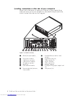
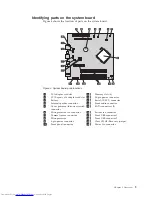


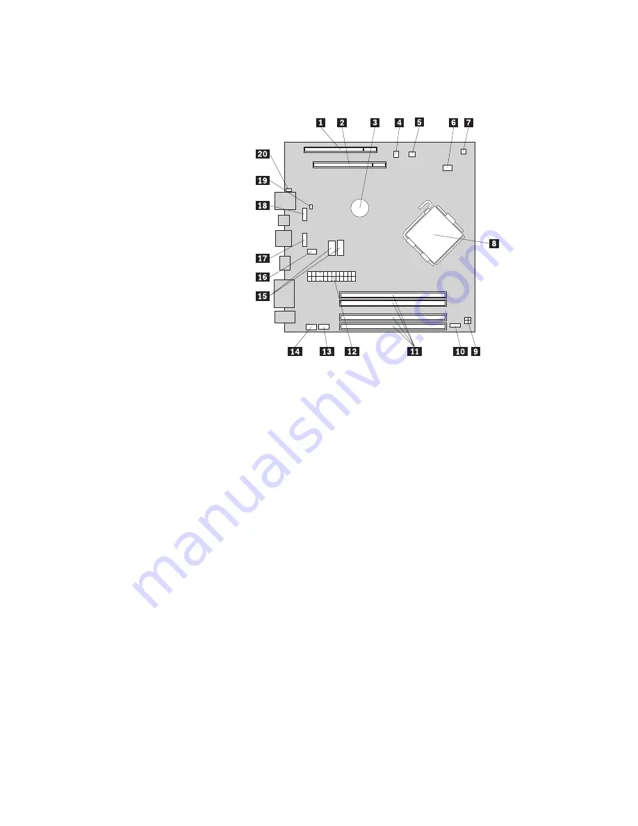
Identifying
parts
on
the
system
board
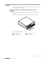
Figure
4
shows
the
location
of
parts
on
the
system
board.
1
PCI
adapter
card
slot
11
Memory
slots
(4)
2
PCI
Express
x16
adapter
card
slot
12
24-pin
power
connector
3
Battery
13
Serial
(COM
2)
connector
4
Internal
speaker
connector
14
Front
audio
connector
5
Cover
presence
(Intrusion)
switch
connector
15
SATA
connectors
(2)
6
Microprocessor
fan
connector
16
System
fan
connector
7
Thermal
sensor
connector
17
Front
USB
connector
1
8
Microprocessor
18
Front
USB
connector
2
9
4-pin
power
connector
19
Clear
CMOS/Recovery
jumper
10
Front
panel
connector
20
Power
fan
connector
Figure
4.
System
board
parts
locations
Chapter
2.
Overview
9
Summary of Contents for ThinkCentre 6137
Page 2: ......
Page 3: ...ThinkCentre Hardware Installation and Replacement Guide ...
Page 6: ...iv ThinkCentre Hardware Installation and Replacement Guide ...
Page 8: ...vi ThinkCentre Hardware Installation and Replacement Guide ...
Page 10: ...2 ThinkCentre Hardware Installation and Replacement Guide ...
Page 18: ...10 ThinkCentre Hardware Installation and Replacement Guide ...
Page 51: ......
Page 52: ...Part Number 46R4690 Printed in USA 1P P N 46R4690 ...


