


Installing
a
drive
in
bay
1
To
install
an
optical
drive
or
an
additional
hard
disk
drive
in
bay
1,
do
the
following:
1.
Remove
the
computer
cover.
See
“Removing
the
cover”
on
page
9.
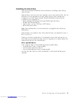
2.
Access
the
system
board.
See
“Accessing
system
board
components
and
drives”
on
page
10.
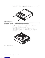
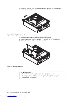
3.
If
you
are
installing
a
drive
with
accessible
media,
such
as
an
optical
drive,
remove
the
plastic
panel
in
the
bezel
by
squeezing
the
plastic
tabs
that
secure
the
panel
on
the
inside
of
the
bezel.
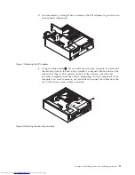
4.
Remove
the
metal
shield
from
the
drive
bay.
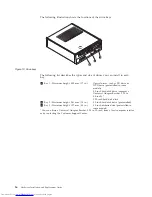
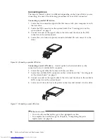
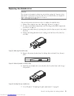
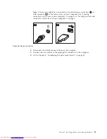
5.
For
a
5.25-inch
drive,
install
a
retainer
bracket
on
the
side
of
the
drive.
Note:
If
you
are
installing
a
3.5-inch
hard
disk
drive
you
must
use
a
Universal
Adapter
Bracket,
5.25
to
3.5-inch.
You
can
obtain
this
bracket
from
a
local
computer
retailer
or
by
contacting
the
Customer
Support
Center.
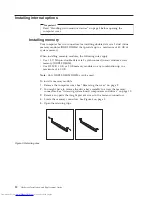
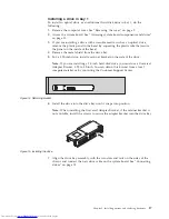
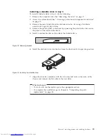
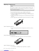
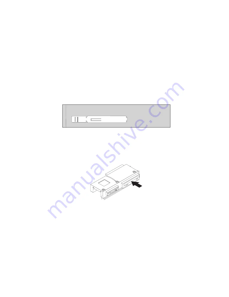
6.
Install
the
drive
into
the
drive
bay
until
it
snaps
into
position.
Note:
When
installing
the
Universal
Adapter
Bracket,
if
the
retainer
bracket
is
not
available,
install
the
screws
to
secure
the
adapter
bracket
into
the
drive
bay.
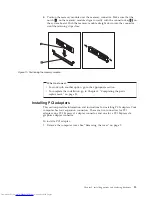
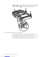
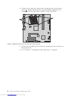
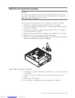
7.
Align
the
drive
bay
assembly
with
the
two
slots
and
rails
on
the
sides
of
the
chassis
and
connect
the
new
drive
cable
on
the
system
board.
See
“Connecting
drives”
on
page
18.
Figure
14.
Retaining
bracket
Figure
15.
Installing
the
drive
Chapter
3.
Installing
options
and
replacing
hardware
17
Summary of Contents for ThinkCentre 7096
Page 2: ......
Page 3: ...ThinkCentre Hardware Installation and Replacement Guide ...
Page 6: ...iv Hardware Installation and Replacement Guide ...
Page 8: ...vi Hardware Installation and Replacement Guide ...
Page 10: ...2 Hardware Installation and Replacement Guide ...
Page 40: ...32 Hardware Installation and Replacement Guide ...
Page 46: ...38 Hardware Installation and Replacement Guide ...
Page 49: ......
Page 50: ...Part Number 45C6431 Printed in USA 1P P N 45C6431 ...


