


3.
Locate
the
Clear
CMOS/Recovery
jumper
on
the
system
board.
See
“Locating
parts
on
the
system
board”
on
page
8.
4.
Move
the
jumper
from
the
standard
position
(pins
1
and
2)
to
the
maintenance
or
configure
position
(pins
2
and
3).
5.
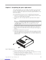
Replace
the
computer
cover
and
connect
the
power
cord.
See
Figure
39
on
page
33.
6.
Restart
the
computer,
leave
it
on
for
approximately
ten
seconds.
Turn
off
the
computer
by
holding
the
power
switch
for
approximately
five
seconds.
The
computer
will
turn
off.
7.
Repeat
steps
1
through
3
on
page
36.
8.
Move
the
Clear
CMOS/Recovery
jumper
back
to
the
standard
position
(pins
1
and
2).
9.
Replace
the
computer
cover
and
connect
the
power
cord.
See
Chapter
4,
“Completing
the
parts
replacement,”
on
page
33.
Chapter
5.
Security
features
37
Summary of Contents for ThinkCentre 7096
Page 2: ......
Page 3: ...ThinkCentre Hardware Installation and Replacement Guide ...
Page 6: ...iv Hardware Installation and Replacement Guide ...
Page 8: ...vi Hardware Installation and Replacement Guide ...
Page 10: ...2 Hardware Installation and Replacement Guide ...
Page 40: ...32 Hardware Installation and Replacement Guide ...
Page 46: ...38 Hardware Installation and Replacement Guide ...
Page 49: ......
Page 50: ...Part Number 45C6431 Printed in USA 1P P N 45C6431 ...


