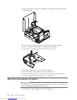
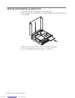
10.
Go
to
“Completing
the
FRU
replacement..”
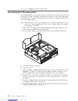
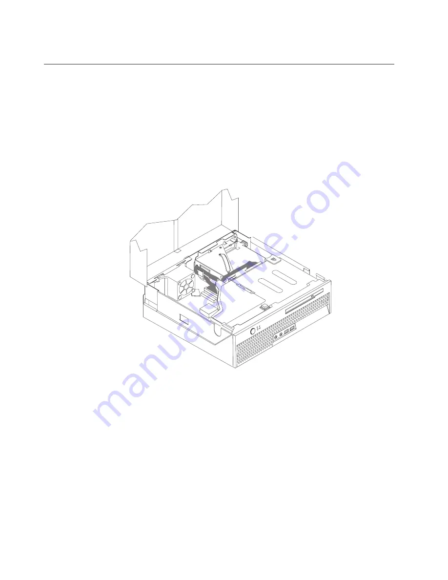
Completing
the
FRU
replacement.
After
replacing
FRUs,
you
need
to
install
any
removed
parts,
replace
the
cover,
and
reconnect
any
cables,
including
telephone
lines
and
power
cords.
Also,
depending
on
the
FRU
that
is
replaced,
you
might
need
to
confirm
the
updated
information
in
the
Setup
Utility
program.
Note:
When
the
power
cord
is
first
plugged
in,
the
computer
might
appear
to
turn
on
for
a
few
seconds
and
then
turn
off.
This
is
a
normal
sequence
to
enable
the
computer
to
initialize.
1.
Ensure
that
all
components
have
been
reassembled
correctly
and
that
no
tools
or
loose
screws
are
left
inside
your
computer.
2.
Make
sure
the
cables
are
correctly
routed
and
are
retained
by
the
cable
clips.
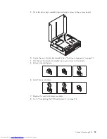
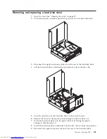
3.
Lower
the
drive
bay
assembly.
4.
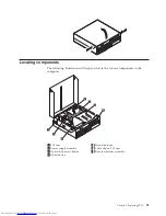
Close
the
cover.
5.
If
your
computer
is
being
placed
in
the
vertical
position,
attach
the
floor
stand.
Attention:
To
prevent
overheating
and
possible
component
damage,
always
attach
the
floor
stand
when
placing
the
computer
in
the
vertical
position.
6.
Reconnect
the
external
cables
and
power
cords
to
the
computer.
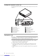
See
“Locating
connectors
on
the
front”
on
page
89
and
“Locating
the
connectors
on
the
rear”
on
page
90.
7.
If
you
have
replaced
the
system
board,
you
must
update
(flash)
the
BIOS.
See
“Flash
update
procedures”
on
page
150.
8.
Some
FRU
replacements
rquire
the
configuration
to
be
updated.
See
Chapter
6,
“Using
the
Setup
Utility,”
on
page
53.
104
Hardware
Maintenance
Manual
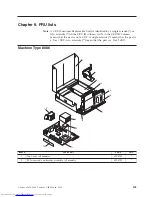
Summary of Contents for ThinkCentre 8086
Page 1: ...Hardware Maintenance Manual Types 8086 8087 8088 8089 Types 8090 8094 ...
Page 2: ......
Page 3: ...Hardware Maintenance Manual Types 8086 8087 8088 8089 Types 8090 8094 ...
Page 18: ...12 Hardware Maintenance Manual ...
Page 19: ...Chapter 2 Safety information 13 ...
Page 20: ... 18 kg 37 lbs 32 kg 70 5 lbs 55 kg 121 2 lbs 1 2 14 Hardware Maintenance Manual ...
Page 24: ...18 Hardware Maintenance Manual ...
Page 25: ...1 2 Chapter 2 Safety information 19 ...
Page 26: ...20 Hardware Maintenance Manual ...
Page 27: ...Chapter 2 Safety information 21 ...
Page 28: ...1 2 22 Hardware Maintenance Manual ...
Page 35: ...Chapter 2 Safety information 29 ...
Page 36: ...30 Hardware Maintenance Manual ...
Page 37: ...1 2 Chapter 2 Safety information 31 ...
Page 41: ...Chapter 2 Safety information 35 ...
Page 42: ...1 2 36 Hardware Maintenance Manual ...
Page 43: ...Chapter 2 Safety information 37 ...
Page 52: ...46 Hardware Maintenance Manual ...
Page 154: ...148 Hardware Maintenance Manual ...
Page 160: ...154 Hardware Maintenance Manual ...
Page 163: ......
Page 164: ...Part Number 19R2387 Printed in USA 1P P N 19R2387 ...


