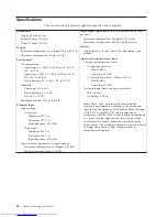
background image

Specifications


This


section


lists


the


physical


specifications


for


your


computer.


Dimensions


Height:


89


mm


(3.5


in.)


Width:


276


mm


(10.9


in.)


Depth:


273


mm


(10.7


in)

Weight


Minimum


configuration


as


shipped:


6.0


kg


(13.2


lb)


Maximum


configuration:


6.4


kg


(14.0


lb)

Environment


Air


temperature:


Operating


at


0


-


3000


ft


(914.4


m):


10°


to


35°C


(50°


to


95°F)


Operating


at


3000


ft


-


7000


ft


(2134


m):


10°


to


32°C


(50°


to


89.6°F)


Non-operating:


10°


to


43°C


(50°


to


110°F)


Humidity:


Operating:


8%


to


80%


Non-operating:


8%


to


80%


Transit:


8%


to


90%


Maximum


altitude:


2134


m


(7000


ft)

Electrical


input


Input


voltage:


Low


range:


Minimum:


100


V


ac


Maximum:


127


V


ac


Input


frequency:


50/60


Hz


High


range:


Minimum:


200


V


ac


Maximum:


240


V


ac


Input


frequency:


50/60


Hz


Input


kilovolt-amperes


(kVA)


(approximate):


Minimum


configuration


as


shipped:


0.09


kVA


Maximum


configuration:


0.23


kVA


Heat


output


(approximate)


in


British


thermal


units


(Btu)


per


hour:


Minimum


configuration:


256


Btu/hr


(75


watts)


Maximum


configuration:


682


Btu/hr


(200


watts)

Airflow


Approximately


14


cubic


feet


(0.45


cubic


meters)


per


minute

Acoustical


noise-emission


values


Average


sound-pressure


levels:


At


operator


position:


Idle:


29


dBA


Operating:


34


dBA


At


bystander


position


-


1


meter


(3.3


ft):


Idle:


28


dBA


Operating:


30


dBA


Declared


(upper


limit)


sound-power


levels:


Idle:


4.0


bels


Operating:


4.3


bels


Note:


These


levels


were


measured


in


controlled


acoustical


environments


according


to


the


procedures


specified


by


the


American


National


Standards


Institute


(ANSI)


S12.10


and


ISO


7779


and


are


reported


in


accordance


with


ISO


9296.


Actual


sound-pressure


levels


in


a


given


location


might


exceed


the


average


values


stated


because


of


room


reflections


and


other


nearby


noise


sources.


The


declared


sound-power


levels


indicate


an


upper


limit,


below


which


a


large


number


of


computers


will


operate.


42


Hardware


Maintenance


Manual

Summary of Contents for ThinkCentre 8086

Page 1: ...Hardware Maintenance Manual Types 8086 8087 8088 8089 Types 8090 8094 ...

Page 2: ......

Page 3: ...Hardware Maintenance Manual Types 8086 8087 8088 8089 Types 8090 8094 ...

Page 4: ...mputer software and services have been developed exclusively at private expense and are sold to governmental entities as commercial items as defined by 48 C F R 2 101 with limited and restricted rights to use reproduction and disclosure LIMITED AND RESTRICTED RIGHTS NOTICE If products data computer software or services are delivered pursuant a General Services Administration GSA contract use repro...

Page 5: ...password 55 Using Security Profile by Device 55 Selecting a startup device 56 Selecting a temporary startup device 56 Changing the startup device sequence 56 Advanced settings 56 Chapter 7 Symptom to FRU Index 57 Hard disk drive boot error 57 Power Supply Errors 57 Diagnostic error codes 59 Beep symptoms 80 No beep symptoms 82 POST error codes 83 Miscellaneous error messages 86 Undetermined proble...

Page 6: ...PI BIOS 152 Automatic Power On features 152 Recovering software using the Rescue and Recovery program 153 Starting the Rescue and Recovery workspace 153 Appendix Notices 155 Television output notice 156 Trademarks 156 iv Hardware Maintenance Manual ...

Page 7: ...also available at http www lenovo com think support Important Safety Information Be sure to read all caution and danger statements in this book before performing any of the instructions Veuillez lire toutes les consignes de type DANGER et ATTENTION du présent document avant d exécuter les instructions Lesen Sie unbedingt alle Hinweise vom Typ ACHTUNG oder VORSICHT in dieser Dokumentation bevor Sie...

Page 8: ...M will have the 4 digit MT and 3 digit CTO model only Example 8129 CTO Again CMVs are custom models and are not found in the HMM General Announce Variant GAV This is a standard model fixed configuration GAVs are announced and offered to all customers The MTM portion of the machine label is a 4 digit MT and 3 digit model where model a fixed model number not CTO Example 8129 F1U Also PEW eSupport an...

Page 9: ...shipped with your system For the remaining FRUs the complete list of FRUs at the MT Model level v eSupport can be used to view the complete list of FRUs for a machine type and model v To view the complete list of FRUs for a machine type 1 Point your browser to http www lenovo com think support 2 Type the machine type Example 8129 in the Use Quick Path field then click Go 3 Under Browse by product ...

Page 10: ...entified as compliant in the system HMM or direct substitutions for those FRUs can be used Products marketed before June 2006 Products marketed after June 2006 Current or original part Replacement FRU Current or original part Replacement FRU Non RoHS Can be Non RoHS Must be RoHS Must be RoHS Non RoHS Can be RoHS Non RoHS Can sub to RoHS RoHS Must be RoHS Note A direct substitution is a part with a...

Page 11: ...t in a hazardous position v Place removed covers and other parts in a safe place away from all personnel while you are servicing the machine v Keep your tool case away from walk areas so that other people will not trip over it v Do not wear loose clothing that can be trapped in the moving parts of a machine Ensure that your sleeves are fastened or rolled up above your elbows If your hair is long f...

Page 12: ... the machine unplug the power cord If you cannot unplug it ask the customer to power off the wall box that supplies power to the machine and to lock the wall box in the off position v If you need to work on a machine that has exposed electrical circuits observe the following precautions Ensure that another person familiar with the power off controls is near you Remember Another person must be ther...

Page 13: ... items However good judgment should be used to identify potential safety hazards due to attachment of features or options not covered by this inspection guide If any unsafe conditions are present you must determine how serious the apparent hazard could be and whether you can continue without first correcting the problem Consider these conditions and the safety hazards they present v Electrical haz...

Page 14: ...ts in protective packages until they are inserted into the product v Avoid contact with other people v Wear a grounded wrist strap against your skin to eliminate static on your body v Prevent the part from touching your clothing Most clothing is insulative and retains a charge even when you are wearing a wrist strap v Use the black side of a grounded work mat to provide a static free work surface ...

Page 15: ... be attached to this product v When possible use one hand only to connect or disconnect signal cables v Never turn on any equipment when there is evidence of fire water or structural damage v Disconnect the attached power cords telecommunications systems networks and modems before you open the device covers unless instructed otherwise in the installation and configuration procedures v Connect and ...

Page 16: ...D ROMs DVD ROM drives fiber optic devices or transmitters are installed note the following v Do not remove the covers Removing the covers of the laser product could result in exposure to hazardous laser radiation There are no serviceable parts inside the device v Use of controls or adjustments or performance of procedures other than those specified herein might result in hazardous radiation exposu...

Page 17: ...nt supplied to the device The device also might have more than one power cord To remove all electrical current from the device ensure that all power cords are disconnected from the power source 1 2 CAUTION Do not place any object weighing more than 82 kg 180 lbs on top of rack mounted devices Chapter 2 Safety information 11 ...

Page 18: ...12 Hardware Maintenance Manual ...

Page 19: ...Chapter 2 Safety information 13 ...

Page 20: ... 18 kg 37 lbs 32 kg 70 5 lbs 55 kg 121 2 lbs 1 2 14 Hardware Maintenance Manual ...

Page 21: ...dência de fogo água ou danos estruturais v Antes de abrir tampas de dispositivos desconecte cabos de alimentação sistemas de telecomunicação redes e modems conectados a menos que especificado de maneira diferente nos procedimentos de instalação e configuração v Conecte e desconecte os cabos conforme descrito na tabela apresentada a seguir ao instalar mover ou abrir tampas deste produto ou de dispo...

Page 22: ...sitivos de fibra ótica ou transmissores estiverem instalados observe o seguinte v Não remova as tampas A remoção das tampas de um produto a laser pode resultar em exposição prejudicial à radiação de laser Não existem peças que podem ser consertadas no interior do dispositivo v A utilização de controles ou ajustes ou a execução de procedimentos diferentes dos especificados aqui pode resultar em exp...

Page 23: ...ida ao dispositivo O dispositivo também pode ter mais de um cabo de alimentação Para remover toda a corrente elétrica do dispositivo assegure que todos os cabos de alimentação estejam desconectados da fonte de alimentação 1 2 CUIDADO Não coloque nenhum objeto com mais de 82 kg 180 lbs sobre dispositivos montados em rack Chapter 2 Safety information 17 ...

Page 24: ...18 Hardware Maintenance Manual ...

Page 25: ...1 2 Chapter 2 Safety information 19 ...

Page 26: ...20 Hardware Maintenance Manual ...

Page 27: ...Chapter 2 Safety information 21 ...

Page 28: ...1 2 22 Hardware Maintenance Manual ...

Page 29: ...irer les carters de l unité mettez celle ci hors tension et déconnectez ses cordons d alimentation ainsi que les câbles qui la relient aux réseaux aux systèmes de télécommunication et aux modems sauf instruction contraire mentionnée dans les procédures d installation et de configuration v Lorsque vous installez que vous déplacez ou que vous manipulez le présent produit ou des périphériques qui lui...

Page 30: ...n en vigueur ATTENTION Si des produits à laser tels que des unités de CD ROM de DVD ROM des unités à fibres optiques ou des émetteurs sont installés prenez connaissance des informations suivantes v Ne retirez pas le carter En ouvrant l unité de CD ROM ou de DVD ROM vous vous exposez au rayonnement dangereux du laser Aucune pièce de l unité n est réparable v Pour éviter tout risque d exposition au ...

Page 31: ...eur dubloc d alimentation ne coupent pas le courant électrique alimentantl unité En outre le système peut être équipé de plusieurs cordonsd alimentation Pour mettre l unité hors tension vous devez déconnectertous les cordons de la source d alimentation 1 2 ATTENTION Ne placez pas d objet supérieur à 82 kg sur une unité montée en armoire Chapter 2 Safety information 25 ...

Page 32: ...rbindung zu den angeschlossenen Netzkabeln Telekommunikationssystemen Netzwerken und Modems ist vor dem Öffnen des Gehäuses zu unterbrechen sofern in den Installations und Konfigurationsprozeduren keine anders lautenden Anweisungen enthalten sind v Zum Installieren Transportieren und Öffnen der Abdeckungen des Computers oder der angeschlossenen Einheiten die Kabel gemäß der folgenden Tabelle ansch...

Page 33: ...ermüll beachten ACHTUNG Bei der Installation von Lasergeräten wie CD ROM Laufwerken DVD aufwerken Einheiten mit Lichtwellenleitertechnik oder Sendern Folgendes beachten v Die Abdeckungen nicht entfernen Durch Entfernen der Abdeckungen des Lasergeräts können gefährliche Laserstrahlungen freigesetzt werden Das Gerät enthält keine zu wartenden Teile v Werden Steuerelemente Einstellungen oder Durchfüh...

Page 34: ...ung für die Einheit nicht unterbrochen Die Einheit kann auch mit mehreren Netzkabeln ausgestattet sein Um die Stromversorgung für die Einheit vollständig zu unterbrechen müssen alle zum Gerät führenden Netzkabel vom Netz getrennt werden 1 2 ACHTUNG Legen Sie auf in einem Rack montierten Einheiten keine über 82 kg schweren Gegenstände ab 28 Hardware Maintenance Manual ...

Page 35: ...Chapter 2 Safety information 29 ...

Page 36: ...30 Hardware Maintenance Manual ...

Page 37: ...1 2 Chapter 2 Safety information 31 ...

Page 38: ...di incendi perdite d acqua o danno strutturale v Scollegare i cavi di alimentazione i sistemi di telecomunicazione le reti e il modem prima di aprire i coperchi del dispositivo salvo istruzioni contrarie relative alle procedure di installazione e configurazione v Collegare e scollegare i cavi come descritto nella seguente tabella quando vengono effettuate operazioni di installazione spostamento o ...

Page 39: ...R 915 82 e successive disposizioni e disposizioni locali ATTENZIONE Quando vengono installati prodotti laser quali CD ROM unità DVD ROM unità a fibre ottiche o trasmittenti tener presente quanto segue v Non rimuovere gli sportelli L apertura di un unità laser può determinare l esposizione a radiazioni laser pericolose All interno dell unità non vi sono parti su cui effettuare l assistenza tecnica ...

Page 40: ...sattivano l alimentazione corrente fornita all unità E possibile che l unità disponga di più cavi di alimentazione Per disattivare l alimentazione dall unità accertarsi che tutti i cavi di alimentazione siano scollegati dalla fonte di alimentazione 1 2 ATTENZIONE Non collocare oggetti che pesano più di 82 kg 180 lb sulla parte superiore delle unità montante nel rack 34 Hardware Maintenance Manual ...

Page 41: ...Chapter 2 Safety information 35 ...

Page 42: ...1 2 36 Hardware Maintenance Manual ...

Page 43: ...Chapter 2 Safety information 37 ...

Page 44: ...a o daños estructurales v Desconecte los cables de alimentación los sistemas de telecomunicaciones las redes y los módems conectados antes de abrir las cubiertas de los dispositivos a menos que se indique lo contrario en los procedimientos de instalación y configuración v Conecte y desconecte los cables como se describe en la tabla siguiente cuando instale mueva o abra las cubiertas de este produc...

Page 45: ...ÓN Cuando haya productos láser como unidades de CD ROM unidades de DVD dispositivos de fibra óptica o transmisores instalados tenga en cuenta lo siguiente v No quite las cubiertas Si quita las cubiertas del producto láser podría quedar expuesto a radiación láser peligrosa Dentro del dispositivo no existe ninguna pieza que requiera servicio técnico v Si usa controles o ajustes o realiza procedimien...

Page 46: ...tan la corriente eléctrica suministrada al dispositivo Además el dispositivo podría tener más de un cable de alimentación Para suprimir toda la corriente eléctrica del dispositivo asegúrese de que todos los cables de alimentación estén desconectados de la toma de corriente 1 2 PRECAUCIÓN No coloque ningún objeto que pese más de 82 Kg 180 lb encima de dispositivos montados en un bastidor 40 Hardwar...

Page 47: ...ical assistance The Access IBM program is preinstalled on most ThinkCentre products Additional information resources If you have Internet access the most up to date information for your computer is available from the World Wide Web You can find the following information v CRU removal and installation instructions v Publications v Troubleshooting information v Parts information v Downloads and driv...

Page 48: ...ation 0 23 kVA Heat output approximate in British thermal units Btu per hour Minimum configuration 256 Btu hr 75 watts Maximum configuration 682 Btu hr 200 watts Airflow Approximately 14 cubic feet 0 45 cubic meters per minute Acoustical noise emission values Average sound pressure levels At operator position Idle 29 dBA Operating 34 dBA At bystander position 1 meter 3 3 ft Idle 28 dBA Operating 3...

Page 49: ...re information on how to determine and obtain the latest level BIOS see BIOS levels on page 150 Use the following procedure to help determine the cause of the problem 1 Power off the computer and all external devices 2 Check all cables and power cords 3 Set all display controls to the middle position 4 Power on all external devices 5 Power on the computer v Look for displayed error codes v Listen ...

Page 50: ...codes on page 59 v If the test stops and you cannot continue replace the last device tested Problem determination tips Due to the variety of hardware and software combinations that can be encountered use the following information to assist you in problem determination If possible have this information available when requesting assistance from Service Support and Engineering functions v Machine typ...

Page 51: ... cabling 5 Have the same software versions and levels 6 Have the same Diagnostics Diskette version 7 Have the same configuration options set in the system 8 Have the same setup for the operation system control files Comparing the configuration and software set up between working and non working systems will often lead to problem resolution Chapter 4 General Checkout 45 ...

Page 52: ...46 Hardware Maintenance Manual ...

Page 53: ... 59 If an installed device is not recognized by the diagnostics program that device might be defective Starting PC Doctor from the Rescue and Recovery workspace This procedure describes how to start PC Doctor from the Rescue and Recovery workspace 1 If your computer is already on when you start this procedure shut down the operating system and turn off the computer 2 To launch the Rescue and Recov...

Page 54: ...igating through the diagnostics programs Use the cursor movement keys to navigate within the menus v The Enter key is used to select a menu item v The Esc key is used to back up to the previous menu v For online help select F1 Running diagnostics tests There are four ways to run the diagnostic tests v Using the cursor movement keys highlight Run Normal Test or Run Quick Test from the Diagnostics m...

Page 55: ...gits Contains a 2 digit check digit value to ensure the following Diagnostics were run on the specified date Diagnostics were run on the specified computer The diagnostic error code is recorded correctly v Text Description of the error Note See Diagnostic error codes on page 59 for error code listings Fixed disk advanced test FDAT PC Doctor Fixed Disk1 Advanced Test module FDAT is a full featured ...

Page 56: ... an in depth manufacturer supported log of errors on the drive Multitasking To allow simultaneous testing of multiple hard drives whenever possible the FDAT module is written as a set of multitasking functions Each drive under test can run the same test or run a different test at the same time Each subtest is written to handle a single test pass and all test variables are kept track of in a struct...

Page 57: ... for enabling or disabling destructive tests as well as specifying a range of destructive and non destructive sectors on the tested drive This is done through the configuration of the FDAT INI If destructive and non destructive ranges somehow overlap then the overlapped area is considered non destructive For example if users specify both destructive and non destructive ranges as the same then the ...

Page 58: ...ck or Full Erase functions To select the Quick Erase or Full Erase Hard Drive utility use the following procedure 1 Select the UTILITY option on the toolbar and press Enter 2 Select either the QUICK ERASE or FULL ERASE HARD DISK option and follow the instructions Viewing the test log Errors reported by the diagnostic test will be displayed by the program as a failed test To view details of a failu...

Page 59: ...automatically when the power on self test POST detects that hardware has been removed or new hardware has been installed in your computer Viewing and changing settings The Setup Utility program menu lists items that identify system configuration topics When working with the Setup Utility program menu you must use the keyboard The keys used to perform various tasks are displayed at the bottom of ea...

Page 60: ...s If you are responsible for maintaining the settings of several computers you might want to set an Administrator Password After you set an Administrator Password a password prompt is displayed each time you try to access the Setup Utility program If both the user and administrator passwords are set you can type either password However to change any configuration settings you must use your adminis...

Page 61: ...Profile by Device is used to enable or disable user access to the following devices IDE controller When this feature is set to Disable all devices connected to the IDE controller such as hard disk drives or the CD ROM drive are disabled and will not be displayed in the system configuration Diskette Drive Access When this feature is set to Disable the diskette drive cannot be accessed Diskette Writ...

Page 62: ...ee Starting the Setup Utility program on page 53 2 Select Startup 3 Select Startup Sequence See the information displayed on the right side of the screen 4 Select the devices for the Primary Startup Sequence the Automatic Startup Sequence and the Error Startup Sequence 5 Select Exit from the Setup Utility menu and then Save Settings or Save and exit the Setup Utility If you have changed these sett...

Page 63: ... boot error A hard disk drive boot error error codes 1962 and I999030X can have the following causes Error FRU Action The start up drive is not in the boot sequence in configuration Check the configuration and ensure the start up drive is in the boot sequence No operating system installed on the boot drive Install an operating system on the boot drive The boot sector on the start up drive is corru...

Page 64: ...e Power LED Green diagnostic LED Yellow diagnostic LED Action ON ON OFF This is the normal condition of the LEDs when the power is OK OFF OFF OFF v Make sure the power cord is attached to a working electrical outlet v Check the power cord for continuity v If the problem persists replace the power supply OFF after the power button has been pressed ON OFF Replace the system board ON ON ON Replace th...

Page 65: ...e 150 2 Boot block 3 System board 000 026 XXX FLASH data error 1 Flash the system See Flash update procedures on page 150 2 Boot block 3 System board 000 027 XXX BIOS Configuration Setup error 1 Run Setup 2 Flash the system See Flash update procedures on page 150 3 Boot block 4 System board 000 034 XXX BIOS Buffer Allocation failure 1 Reboot the system 2 Flash the system See Flash update procedure...

Page 66: ... Using the Setup Utility on page 53 2 Flash the system and retest See Flash update procedures on page 150 3 Go to Undetermined problems on page 88 000 199 XXX BIOS test failed cause unknown 1 Go to Undetermined problems on page 88 2 Flash the system and re test 3 Replace component under function test 000 250 XXX BIOS APM failure 1 Flash the system See Flash update procedures on page 150 2 System b...

Page 67: ...e 1 Power off on system and re test 2 System board 001 041 XXX System DMA failure 1 Power off on system and re test 2 System board 001 195 XXX System Test aborted by user Information only Re start the test if necessary 001 196 XXX System test halt error threshold exceeded 1 Press F3 to review the log file 2 Re start the test to reset the log file 001 197 XXX System test warning 1 Make sure the com...

Page 68: ... on IRQ3 2 System board 001 271 XXX System IRQ4 failure 1 Device on IRQ4 2 System board 001 272 XXX System IRQ5 failure 1 Device on IRQ5 2 System board 001 273 XXX System IRQ6 diskette drive failure 1 Diskette Cable 2 Diskette drive 3 System board 001 274 XXX System IRQ7 failure 1 Device on IRQ7 2 System board 001 275 XXX System IRQ8 failure 1 Device on IRQ8 2 System board 001 276 XXX System IRQ9 ...

Page 69: ...1 300 XXX System RTC Alarm failure System board 001 301 XXX System RTC Century byte error 1 Flash the system See Flash update procedures on page 150 2 System board 005 000 XXX Video Test Passed No action 005 00X XXX Video error 1 Video card if installed 2 System board 005 010 XXX 005 011 XXX 005 012 XXX 005 013 XXX Video Signal failure 1 Video card if installed 2 System board 005 016 XXX Video Sim...

Page 70: ... that is called out is connected and or enabled See Chapter 6 Using the Setup Utility on page 53 2 Re run test 3 Replace the component called out in warning statement 4 Replace the component under test 005 198 XXX Video test aborted 1 If a component is called out make sure it is connected and or enabled See Chapter 6 Using the Setup Utility on page 53 2 Flash the system and re test See Flash updat...

Page 71: ...ems on page 88 006 199 XXX Diskette interface test failed cause unknown 1 Go to Undetermined problems on page 88 2 Flash the system and re test 3 Replace component under function test 006 25X XXX Diskette interface Error 1 Diskette drive cable 2 Diskette drive 3 System board 011 000 XXX Serial port Interface Test Passed No action 011 001 XXX Serial port Presence 1 Remove external serial device if ...

Page 72: ...procedures on page 150 3 Go to Undetermined problems on page 88 011 199 XXX Serial port test failed cause unknown 1 Go to Undetermined problems on page 88 2 Flash the system and re test See Flash update procedures on page 150 3 Replace component under function test 011 2XX XXX Serial port signal failure 1 External serial device 2 System board 014 000 XXX Parallel port Interface Test Passed No acti...

Page 73: ... the system and re test See Flash update procedures on page 150 3 Go to Undetermined problems on page 88 014 199 XXX Parallel port test failed cause unknown 1 Go to Undetermined problems on page 88 2 Flash the system and re test See Flash update procedures on page 150 3 Replace component under function test 014 2XX XXX 014 3XX XXX Parallel port failure 1 External parallel device 2 System board 015...

Page 74: ... 1 Make sure the component that is called out is connected and or enabled See Chapter 6 Using the Setup Utility on page 53 2 Re run test 3 Replace the component that is called out in warning statement 4 Replace the component under test 015 198 XXX USB port test aborted 1 If a component is called out make sure it is connected and or enabled See Chapter 6 Using the Setup Utility on page 53 2 Flash t...

Page 75: ...CI Card test failed cause unknown 1 Go to Undetermined problems on page 88 2 Flash the system and re test See Flash update procedures on page 150 3 Replace component under function test 018 250 XXX PCI Card Services error 1 PCI card 2 Riser card if installed 3 System board 020 000 XXX PCI Interface Test Passed No action 020 0XX XXX PCI Interface error 1 PCI card 2 Riser card if installed 3 System ...

Page 76: ...at IDE signal cable 4 IDE device 5 System board 025 027 XXX IDE interface Configuration Setup error 1 IDE signal cable 2 Flash the system See Flash update procedures on page 150 3 Reseat IDE signal cable 4 IDE device 5 System board 025 02X XXX 025 03X XXX 025 04X XXX IDE Interface failure 1 IDE signal cable 2 Check power supply 3 Reseat IDE signal cable 4 IDE device 5 System board 025 195 XXX IDE ...

Page 77: ...System board 030 027 XXX SCSI interface Configuration Setup error 1 SCSI signal cable 2 Flash the system See Flash update procedures on page 150 3 SCSI device 4 SCSI adapter card if installed 5 System board 030 03X XXX 030 04X XXX SCSI interface error 1 SCSI signal cable 2 Check power supply 3 SCSI device 4 SCSI adapter card if installed 5 System board 030 195 XXX SCSI interface Test aborted by us...

Page 78: ...035 196 XXX RAID interface test halt error threshold exceeded 1 Press F3 to review the log file 2 Re start the test to reset the log file 035 197 XXX RAID interface test warning 1 Make sure the component that is called out is connected and or enabled See Chapter 6 Using the Setup Utility on page 53 2 Re run test 3 Replace the component that is called out in warning statement 4 Replace the componen...

Page 79: ...e run test 3 Replace the component that is called out in warning statement 4 Replace the component under test 071 198 XXX Audio port test aborted 1 If a component is called out make sure it is connected and or enabled See Chapter 6 Using the Setup Utility on page 53 2 Flash the system and re test See Flash update procedures on page 150 3 Go to Undetermined problems on page 88 071 199 XXX Audio por...

Page 80: ... on page 150 3 Go to Undetermined problems on page 88 080 199 XXX Game Port interface test failed cause unknown 1 See Undetermined problems on page 88 2 Flash the system and re test See Flash update procedures on page 150 3 Replace component under function test 086 000 XXX Mouse Port interface Test Passed No action 086 001 XXX Mouse Port interface Presence 1 Mouse 2 System board 086 032 XXX Mouse ...

Page 81: ...r Test Passed No action 089 XXX XXX Microprocessor failure 1 Microprocessor s 2 System board 089 195 XXX Microprocessor Test aborted by user Information only Re start the test if necessary 089 196 XXX Microprocessor test halt error threshold exceeded 1 Press F3 to review the log file 2 Re start the test to reset the log file 089 197 XXX Microprocessor test warning 1 Make sure the component that is...

Page 82: ...g the Setup Utility on page 53 2 Flash the system and re test See Flash update procedures on page 150 3 Go to Undetermined problems on page 88 170 199 XXX Voltage Sensor s test failed cause unknown 1 See Undetermined problems on page 88 2 Flash the system and re test See Flash update procedures on page 150 3 Replace component under function test 170 250 XXX 170 251 XXX Voltage Sensor s Voltage lim...

Page 83: ...ures on page 150 3 Replace component under function test 175 250 XXX 175 251 XXX Thermal Sensor s limit error 1 Check fans 2 Check Power supply voltages 3 Microprocessor 4 System board 185 000 XXX Asset Security Test Passed No action 185 XXX XXX Asset Security failure 1 Flash system 2 System board 185 278 XXX Asset Security Chassis Intrusion 1 Assure Asset Security Enabled 2 C2 Cover Switch 3 Syst...

Page 84: ...ard Disk drive SCSI 5 SCSI adapter card 6 System board 220 000 XXX Hi Capacity Cartridge Drive Test Passed No action 220 XXX XXX Hi Capacity Cartridge Drive error 1 Remove the Hi Capacity Cartridge Drive and re test the system 301 XXX XXX Keyboard error 1 Keyboard 2 Check and test mouse 3 System board 301 000 XXX Keyboard Test Passed No action 302 000 XXX Mouse Test Passed No action 302 XXX XXX Mo...

Page 85: ...Diagnostic Error Code FRU Action 415 000 XXX Modem Test Passed No action 415 XXX XXX Modem error Remove the Modem and re test the system Chapter 7 Symptom to FRU Index 79 ...

Page 86: ...DMA page register write read failed System board 1 2 4 RAM refresh verification failed 1 Memory module 2 System Board 1 3 3 1 1st 64K RAM test failed 1 Memory module 2 System Board 1 3 2 1st 64K RAM parity test failed 1 Memory module 2 Processor 3 System Board 2 2 3 1 Interrupt vector loading test failed System board 2 1 1 Secondary DMA register failed System board 2 1 2 Primary DMA register faile...

Page 87: ...Jumper on J28 2 System Board 2 3 2 Screen memory failed System board 2 3 3 Screen retrace failed System board 1 2 Search for video ROM failed System board All other beep code sequences System board Continuous beep System Board Repeating short beeps 1 Keyboard stuck key 2 Keyboard Cable 3 System Board Chapter 7 Symptom to FRU Index 81 ...

Page 88: ... beep during POST but computer works correctly System board No beep during POST 1 See Undetermined problems on page 88 2 System Board 3 Memory Module 4 Any Adapter or Device 5 Riser Card 6 Power Cord 7 Power Supply 82 Hardware Maintenance Manual ...

Page 89: ... Error Code FRU Action 162 Configuration error Select the default settings in BIOS See Chapter 6 Using the Setup Utility on page 53 164 Memory Size Error 1 Run the Extended Memory Diagnostic tests 2 Replace memory modules 166 Boot Block Check Sum Error 1 Perform a flash update to update the BIOS level 2 System board 167 No Processor BIOS update found 1 Run Setup Check Stepping level for the BIOS l...

Page 90: ...d 211 Keyboard error 1 Make sure keyboard is connected correctly 2 Check for stuck keys 3 Replace the keyboard 212 Keyboard controller error 1 Replace the keyboard 2 If problem persists replace the system board 250 Battery is dead 1 Replace the battery and run Setup 2 If problem persists replace the system board 270 Real time clock error 1 Run Setup and set date and time 2 If problem persists repl...

Page 91: ...Error Not Enough Real Memory Space Available 1 Run Setup and verify PCI ISA configuration settings 2 Run diagnostics 3 Replace PCI Adapter 1805 PCI PnP Error Adapter ROM Checksum Error 1 Run Setup and verify PCI ISA configuration settings 2 Run diagnostics 3 Replace PCI Adapter 1962 No operating system found Press F1 to repeat boot sequence 5962 An IDE device other than hard drive configuration er...

Page 92: ...twork adapter 2 Ensure that the operating system settings are set to enable Wake on LAN 3 Ensure Wake on LAN feature is enabled in Setup Configuration see Starting the Setup Utility program on page 53 4 Ensure network administrator is using correct MAC address 5 Ensure no interrupt or I O address conflicts 6 Network adapter advise network administrator of new MAC address Dead computer See Power Su...

Page 93: ...s correctly 1 Power Supply 2 System Board 3 LED Cables Printer problems 1 Printer Program loads from the hard disk with a known good diagnostics diskette in the first 3 5 inch diskette drive 1 Run Setup 2 Diskette Drive 3 Diskette Drive Cable 4 System Board 5 Riser card 6 Power Supply RPL computer cannot access programs from its own hard disk 1 If network administrator is using LCCM Hybrid RPL che...

Page 94: ...r 2 Remove or disconnect the following components if installed one at a time a External devices modem printer or mouse b Any adapters c Riser card d Memory modules e Extended video memory f External Cache g External Cache RAM h Hard disk drive i Diskette drive 3 Power on the computer to re test the system 4 Repeat steps 1 through 3 until you find the failing device or adapter If all devices and ad...

Page 95: ...e by trained service technicians only This chapter does not contain a remove and replace procedure for all FRUs Only the major FRUs are documented Locating connectors on the front The following illustration shows the locations of the USB connectors on the front of the computer 1 Headphone connector 3 USB connector 2 Microphone connector 4 USB connector Lenovo 2005 2008 Portions IBM Corp 2005 89 ...

Page 96: ...tor 14 Power connector Opening the cover Important Read Chapter 2 Safety information on page 5 and Handling electrostatic discharge sensitive devices on page 8 before opening the cover 1 Shut down the operating system remove any media DVDs CDs or tapes from the drives and turn off all attached devices 2 Unplug all power cords from electrical outlets 3 Disconnect all cables attached to the computer...

Page 97: ...ion will help you locate the various components in the computer 1 PCI riser 5 Hard disk drive 2 Power supply assembly 6 Cable clip on PCI riser 3 Optical drive eject button 7 Rear fan bracket assembly 4 Optical drive Chapter 8 Replacing FRUs 91 ...

Page 98: ...or 11 Rear fan connector 5 Power connector 12 SATA connector 6 Front fan connector 13 Clear CMOS Recovery jumper 7 Microprocessor 14 Battery Removing and replacing a memory module 1 Open the cover See Opening the cover on page 90 2 Locate the memory connectors See Identifying parts on the system board 3 Open the retaining clips and remove the failing memory module 92 Hardware Maintenance Manual ...

Page 99: ...taining clips are closed 5 Go to Completing the FRU replacement on page 104 Removing and replacing a PCI adapter This section provides information and instructions for replacing a PCI adapter 1 Open the cover See Opening the cover on page 90 2 Pivot the drive bay assembly upward to gain access to the system board 3 Remove all cables from the cable clip attached to the PCI riser Chapter 8 Replacing...

Page 100: ... Pivot the adapter latch down to retain the adapter 9 Reinstall the PCI riser assembly into the system board 10 Replace all cables that were removed from the cable clip on the PCI riser 11 Go to Completing the FRU replacement on page 104 Removing and replacing the battery Important Refer to Safety notices multi lingual translations on page 9 for information about replacing and disposing of the bat...

Page 101: ...an bracket assembly See Locating components on page 91 4 Lift the rear fan bracket assembly up to gain access to the battery 5 Remove the old battery 6 Install the new battery 7 Replace the rear fan bracket assembly 8 Go to Completing the FRU replacement on page 104 Chapter 8 Replacing FRUs 95 ...

Page 102: ...e no servicable parts inside these components 1 Open the cover See Opening the cover on page 90 2 Remove the PCI riser See Removing and replacing a PCI adapter on page 93 3 Disconnect all power supply cables from the drives 4 Disconnect all power supply cables from the system board See Identifying parts on the system board on page 92 5 Remove the three screws that hold the power supply in place 6 ...

Page 103: ...m board 1 Open the cover See Opening the cover on page 90 2 Remove the PCI riser See Removing and replacing a PCI adapter on page 93 3 Disconnect rear fan cable and remove the rear fan bracket assembly by lifting it off the system board 4 Carefully take note of the location of all cable connections on the system board and disconnect all cables 5 Take note of the location of the memory modules and ...

Page 104: ...ormed by the thermal grease and lifting it straight up 8 Place the heat sink on its side on a clean work surface so that the thermal grease is not contaminated 9 Use the handle at the rear of the system board to pull the system board and tray out the rear of the chassis 98 Hardware Maintenance Manual ...

Page 105: ...ins are aligned with the socket and with the beveled corner 1 on the microprocessor is aligned in the socket as shown 13 Lower and lock the handle to secure the microprocessor in the socket Note Do not install the heatsink until the new system board has been installed 14 Install the new system board and tray into the rear of the chassis until it is fully seated 15 Reinstall the PCI riser 16 Reinst...

Page 106: ...t sink to break the seal formed by the thermal grease and lifting it straight up 4 Place the heat sink on a clean work surface 5 Release the microprocessor 1 from the system board socket by pulling outward and lifting the small handle 2 on the microprocessor socket to its maximum vertical position Carefully lift the microprocessor off the socket 6 Make sure that the microprocessor socket handle is...

Page 107: ...hese must be ordered separately and shipped along with the FRUs being replaced b Be sure that all of the thermal grease is removed Note 0 01ML is one tick mark on the syringe If the grease is properly applied approximately half 0 22ML of the grease will remain in the syringe 10 Use the thermal grease syringe to place 16 uniformly spaced dots of 0 01ML each on the top of the microprocessor Micropro...

Page 108: ...the cover on page 90 2 Push the optical drive eject button and slide the optical drive out of the front of the computer 3 Slide the new drive into the bay until it is latched into position 4 Go to Completing the FRU replacement on page 104 102 Hardware Maintenance Manual ...

Page 109: ...bracket up to remove it from the drive bay 5 Note the orientation of the hard disk drive in the plastic bracket 6 Remove the drive by flexing the plastic enough to slide the drive out 7 Install the hard disk drive into the plastic bracket by flexing the plastic enough to slide the drive in 8 Install the hard disk drive and bracket into the bay until it snaps into position 9 Reconnect the signal an...

Page 110: ...crews are left inside your computer 2 Make sure the cables are correctly routed and are retained by the cable clips 3 Lower the drive bay assembly 4 Close the cover 5 If your computer is being placed in the vertical position attach the floor stand Attention To prevent overheating and possible component damage always attach the floor stand when placing the computer in the vertical position 6 Reconn...

Page 111: ...ID Column means that the part is not a CRU A single asterisk means that the part is a Tier 1 CRU two asterisks mean that the part is a Tier 2 CRU Machine Type 8086 1 2 3 4 5 6 8 7 9 10 11 12 13 Item 8086 FRUs FRU CRU 1 Top Cover all models 89P6782 2 PCI riser card and bracket assembly all models 89P6790 Lenovo 2005 2008 Portions IBM Corp 2005 105 ...

Page 112: ...G A6C A6V A8G 18S 18L 18Y 2BA 2BQ 2BT 2BC 2BB 2BH 2BV 2BK 35C 35B 35H 36S 36P 36L 36D 36Y 36G 36M 36A 36Q 36T 36C 36B 36H 36V 36K 36R 36E 36J CTO AJU AKU ALG 1AU 2FU 3AU 3AF 3AS 3AP 3AL 3AD 3AY 41A 41Q 41T 41B 41H 42U 42F 42S 42P 42L 42D 42Y 42G 43U ARG B2K 1BA 1BQ 1BT 1BV 1DK 40Y8757 4 Hard disk drive 80GB 7200rpm EIDE ATA 100 models 11J 14J A4J 13S 13L 13Y 27E 27J 28J 29J 2AJ A9J 2CJ 38J 39J 26G...

Page 113: ...A8G A9J 18S 18L 18Y 2BA 2BQ 2BT 2BC 2BB 2BH 2BV 2BK 35C 35B 35H 36S 36P 36L 36D 36Y 36G 36M 36A 36Q 36T 36C 36B 36H 36V 36K 36R 36E 36J CTO AEJ AFJ AJU AKU ALG 2GE 2GJ 2HJ 3BE 3BJ 3CJ 41A 41Q 41T 41B 41H 42U 42F 42S 42P 42L 42D 42Y 42G 43U 44E 44J 45J ARG B1B B1H B2K B3K 1BA 1BQ 1BT 1BV 1DK 1EB 1EH 1FK 1HJ 1LJ 3LJ 40Y8907 6 DVD ROM 8x 24x models 26G 37G CTO 1AU 2FU 3AU 3AF 3AS 3AP 3AL 3AD 3AY 49U ...

Page 114: ...409 10 Microprocessor 2 8GHz Northwood Celeron multi VID models A3S A3P A3L A3Y CTO A3U A8S A8Y A8G AKU 19R2411 10 Microprocessor 2 93GHz Northwood Celeron multi VID models CTO U CTO G ALG ARG 29R7261 10 Microprocessor 3 06GHz Northwood Celeron multi VID models CTO U CTO G B1B B1H B2K B3K B4K 29R7263 10 Microprocessor 2 6GHz Northwood P4 multi VID models CTO 19R2421 10 Microprocessor 2 8GHz Northw...

Page 115: ...AGJ AHJ 2DJ 2EJ 2GE 2GJ 2HJ 2KJ 2LJ 2MJ 3AU 3AF 3AS 3AP 3AL 3AD 3AY 3BE 3BJ 3CJ 3EJ 3FJ 3GJ 3HJ 3JJ 3KJ 43U 44E 44J 45J 47J 48J 4AG 4BJ 4DJ 4EJ 4HC 41T2091 11 System board 10 1000 POV models CTO 34U A4J 16U 19U 24U 27E 27J 28J 29J 2AJ 11J 14J 26G 37G A9J 2CJ 38J 39J ACJ ADJ AEJ AFJ AGJ AHJ 2DJ 2EJ 2GE 2GJ 2HJ 2KJ 2LJ 2MJ 3AU 3AF 3AS 3AP 3AL 3AD 3AY 3BE 3BJ 3CJ 3EJ 3FJ 3GJ 3HJ 3JJ 3KJ 43U 44E 44J 4...

Page 116: ...15U 16U 17U 18U 19U 21F 22U 24U 25U 26G 27E 27J 28J 29J 2AJ 32U 35U 36U 36F 37G A5S A5Y A5G A6G A6C A6V A8G A9J 18S 18L 18Y 2BA 2BQ 2BT 2BC 2BB 2BH 2BV 2BK 2CJ 35C 35B 35H 36S 36P 36L 36D 36Y 36G 36M 36A 36Q 36T 36C 36B 36H 36V 36K 36R 36E 36J 38J 39J CTO AEJ AFJ AGJ AHJ AJU AKU ALG 1AU ABU 2FU 2GE 2GJ 2HJ 2JU 2KJ 2LJ 2MJ 3AU 3AF 3AS 3AP 3AL 3AD 3AY 3BE 3BJ 3CJ 3DU 3EJ 3FJ 3GJ 3JJ 3KJ 41A 41Q 89P5...

Page 117: ...6G CTO G ALG 42G 4AG ARG 89P8315 Hungarian models 21G 26G 37G A5G A6G A8G 36G CTO G ALG 42G 4AG ARG 89P8316 Iceland models 21G 26G 37G A5G A6G A8G 36G CTO G ALG 42G 4AG ARG 89P8317 Italian 141 models 21G 26G 37G A5G A6G A8G 36G CTO G ALG 42G 4AG ARG 89P8318 Italian 142 models 21G 26G 37G A5G A6G A8G 36G CTO G ALG 42G 4AG ARG 89P8319 Japanese models 11J 14J A4J 27J 28J 29J 2AJ A9J 2CJ 36J 38J 39J A...

Page 118: ...RU US English models 41A 41Q 41H 4HC CTO 89P8800 Chinese US models 41B CTO A 89P8807 Thailand models 41T CTO A 89P8834 8086 Windows XP Home Recovery CDs FRU CRU US UK AP TH models A6G 39J6250 FR CF models A6G 39J6251 GR models A6G 39J6252 IT models A6G 39J6254 SP LA models A6G 39J6253 DK models A6G 39J6257 NL models A6G 39J6260 AE models A6G 39J6264 SV models A6G 39J6256 HE models A6G 39J6261 FI m...

Page 119: ...6F 37G A5G A8G 36G CTO G ALG 42G 4AG ARG 39J6425 FI models 21G 21F 26G 36F 37G A5G A8G 36G CTO G ALG 42G 4AG ARG 39J6422 NO models 21G 21F 26G 36F 37G A5G A8G 36G CTO G ALG 42G 4AG ARG 39J6423 PL models 21G 21F 26G 36F 37G A5G A8G 36G CTO G ALG 42G 4AG ARG 39J6426 PO models 21G 21F 26G 36F 37G A5G A8G 36G CTO G ALG 42G 4AG ARG 39J6432 RU models 21G 21F 26G 36F 37G A5G A8G 36G CTO G ALG 42G 4AG ARG...

Page 120: ...EMEA LA models A3S A3P A3L A3Y 21S 22S 22P 22L 22Y 32S 32P 32L 32Y 21G A8S A8Y 13S 13L 13Y 26G 37G A5S A5Y A5G A6G A8G 18S 18L 18Y 36S 36P 36L 36D 36Y 36G CTO G ALG 3AS 3AP 3AL 3AD 3AY 42S 42P 42L 42D 42Y 42G 46S 46P 46L 46D 46Y 49S 49P 49L 49D 49Y 4AG ARG 14F0068 Power Cord APU models A3Y 22Y 32Y A8Y 13Y A5Y 18Y 36Y 3AY 42Y 46Y 49Y 36L8879 Power Cord Japan models 11J 14J A4J 27E 27J 28J 29J 2AJ A...

Page 121: ... 36V 36K 36R 36J 36Q 36E 35M CTO A1M 21M 19K1568 4 Hard disk drive 40GB 7200rpm EIDE ATA 100 models 36U 36F 36S 36P 36L 36D 36Y 36G 36M 36A 36T 36C 36B 36H 36V 36K 36R 36J 36Q 36E 35M CTO A1M 21M 40Y8757 4 Hard disk drive 40GB 7200rpm Serial ATA models CTO 71P7312 4 Hard disk drive 80GB 7200rpm EIDE ATA 100 models CTO 22M 24P3665 4 Hard disk drive 80GB 7200rpm EIDE ATA 100 models CTO 22M 40Y8758 4...

Page 122: ...8783 6 DVD ROM CD RW Combo Drive 24x24x24x8x models CTO 22M 26K5409 6 DVD ROM CD RW Combo Drive 24x24x24x8x models CTO 22M 40Y8785 6 Rambo4 slim models CTO 26K5421 6 Multi Burner Plus Rambo 4 Ultrabay Enhanced Drive models CTO 40Y8789 7 Main Bezel assembly all models 39M0613 8 Speaker Cable assembly all models 03R0294 9 Heat Sink models 36U 36F 36S 36P 36L 36D 36Y 36G 36M 36A 36T 36C 36B 36H 36V 3...

Page 123: ...1M 21M 22M 41T2093 12 Memory 128MB NP SDRAM PC2700 models CTO 31P9120 12 Memory 256MB NP SDRAM PC2700 models CTO 31P9121 12 Memory 512MB NP SDRAM PC2700 models CTO A1M 31P9122 12 Memory 1 GB NP SDRAM PC2700 models CTO 31P9123 12 Memory 128MB NP SDRAM PC3200 models CTO 22P9273 12 Memory 256MB NP SDRAM PC3200 models CTO 73P2683 12 Memory 512MB NP SDRAM PC3200 models 36U 36F 36S 36P 36L 36D 36Y 36G 3...

Page 124: ... models 60H6047 RJ11 connector adapter Norway Finland All G models 60H6048 RJ11 connector adapter France All G models 60H6049 RJ11 connector adapter Germany All G models 60H6050 RJ11 connector adapter UK NZ HK All G M B H models 60H6051 RJ11 connector adapter Italy All G models 60H6052 RJ11 connector adapter Netherlands All G models 60H6053 RJ11 connector adapter Sweden All G models 60H6054 RJ11 c...

Page 125: ...dels 36G CTO G 89P8330 Spanish models 36G CTO G 89P8331 Swedish Finn models 36G CTO G 89P8332 Swiss F G models 36G CTO G 89P8333 Thailand models 36T CTO A 89P8334 Turkish 440 models 36G CTO G 89P8335 Turkish 179 models 36G CTO G 89P8336 UK English models 36G CTO G 89P8337 US Euro models 36G CTO G 89P8338 Yugoslav Latin models 36G CTO G 89P8339 Brazil Portuguese models 36P CTO L 89P8304 8087 Window...

Page 126: ...G 39J6420 DK models 36G 39J6421 FI models 36G 39J6422 NO models 36G 39J6423 NL models 36G 39J6424 HE models 36G 39J6425 PL models 36G 39J6426 CZ models 36G 39J6427 AE models 36G 39J6428 RU models 36G 41D1950 RE models 36G 41D1949 TR models 36G 39J6430 HU models 36G 39J6431 PO models 36G 39J6432 GK models 36G 39J6433 SL models 36G 39J6434 JP models 36J 30R4834 CS models 36C 30R4820 Taiwan TC models...

Page 127: ... Cord EMEA models 36G CTO G 13F9996 Power Cord EMEA LA models 36S 36P 36L 36D 36Y 36G CTO G 14F0068 Power Cord APU models 36Y 36L8879 Power Cord Japan models 36J 36E 1838576 Power Cord China HK models 36C 36B 36H 02K0545 Power Cord EMEA models 36G CTO G 14F0086 Power Cord EMEA ANZ ASEAN Eng models 36G CTO G 14F0014 Power Cord EMEA models 36G CTO G 14F0050 Power Cord India models 36Q 49P2055 Chapte...

Page 128: ...1568 4 Hard disk drive 40GB 7200rpm EIDE ATA 100 models 99U 99F 99S 99P 99L 99D 99Y 99G 99M 99A 99Q 99T 99C 99B 99H 99V 99K 99J CTO 40Y8757 4 Hard disk drive 40GB 7200rpm Serial ATA models CTO 71P7312 4 Hard disk drive 80GB 7200rpm EIDE ATA 100 models CTO 24P3665 4 Hard disk drive 80GB 7200rpm EIDE ATA 100 models CTO 40Y8758 4 Hard disk drive 120GB 7200rpm EIDE ATA 100 models CTO 24P3687 4 Hard di...

Page 129: ...CD RW Combo Drive 24x24x24x8x models CTO 40Y8785 6 Rambo 4 slim models CTO 26K5421 6 Multi Burner Plus Rambo 4 Ultrabay Enhanced Drive models CTO 40Y8789 7 Main Bezel assembly all models 39M0613 8 Speaker Cable assembly all models 03R0294 9 Heat Sink models 99U 99F 99S 99P 99L 99D 99Y 99G 99M 99A 99Q 99T 99C 99B 99H 99V 99K 99J CTO 89P6791 10 Microprocessor 2 4GHZ Northwood Celeron models CTO 19R1...

Page 130: ... PC2700 models CTO 31P9122 12 Memory 1 GB NP SDRAM PC2700 models CTO 31P9123 12 Memory 128MB NP SDRAM PC3200 models CTO 22P9273 12 Memory 256MB NP SDRAM PC3200 models CTO 73P2683 12 Memory 512MB NP SDRAM PC3200 models 99U 99F 99S 99P 99L 99D 99Y 99G 99M 99A 99Q 99T 99C 99B 99H 99V 99K 99J CTO 73P2684 12 Memory 1GB NP SDRAM PC3200 models CTO 22P9274 13 50 mm exhaust fan all models 89P6789 The FRUs ...

Page 131: ...or adapter France All G models 60H6049 RJ11 connector adapter Germany All G models 60H6050 RJ11 connector adapter UK NZ HK All G M B H models 60H6051 RJ11 connector adapter Italy All G models 60H6052 RJ11 connector adapter Netherlands All G models 60H6053 RJ11 connector adapter Sweden All G models 60H6054 RJ11 connector adapter Switzerland All G models 60H6055 8088 Keyboards Standard PS 2 Black FR...

Page 132: ...32 Swiss F G models 99G CTO G 89P8333 Thailand models 36T CTO A 89P8334 Turkish 440 models 99G CTO G 89P8335 Turkish 179 models 99G CTO G 89P8336 UK English models 99G CTO G 89P8337 US Euro models 99G CTO G 89P8338 Yugoslav Latin models 99G CTO G 89P8339 Brazil Portuguese models 36P CTO L 89P8304 8088 Windows XP Home Recovery CDs FRU CRU US UK AP TH models CTO 39J6250 FR CF models CTO 39J6251 GR m...

Page 133: ...s 99G 39J6423 PL models 99G 39J6426 PO models 99G 39J6432 RU models 99G 41D1950 RE models 99G 41D1949 HU models 99G 39J6431 CZ models 99G 39J6427 TR models 99G 39J6430 GK models 99G 39J6433 SL models 99G 39J6434 JP models 99J 30R4834 CS models 99C 30R4820 Taiwan TC models 99V 30R4820 Hong Kong TC models 99B 30R4827 Korean models 99K 30R4806 Multilingual 1 models 99G 39J7221 Multilingual 2 models 9...

Page 134: ...d APU models 99Y 36L8879 Power Cord Japan models 99J 1838576 Power Cord China HK models 99C 99B 99H 02K0545 Power Cord EMEA models 99G 14F0086 Power Cord EMEA ANZ ASEAN Eng models 99G 14F0014 Power Cord EMEA models 99G 14F0050 Power Cord India models 99Q 49P2055 128 Hardware Maintenance Manual ...

Page 135: ...CTO 31U 32U 76G 13G 19K1568 4 Hard disk drive 40GB 7200rpm EIDE ATA 100 models 11U 12U 21U 22U 72G 74G 75G CTO 31U 32U 76G 13G 40Y8757 4 Hard disk drive 40GB 7200rpm Serial ATA models CTO 71P7312 4 Hard disk drive 80GB 7200rpm EIDE ATA 100 models 71G 73G CTO 23S 23D 77G 24P3665 4 Hard disk drive 80GB 7200rpm EIDE ATA 100 models 71G 73G CTO 23S 23D 77G 40Y8758 4 Hard disk drive 120GB 7200rpm EIDE A...

Page 136: ...3 6 DVD ROM CD RW Combo Drive 24x24x24x8x models 12U 22U CTO 23S 23D 32U 77G 26K5409 6 DVD ROM CD RW Combo Drive 24x24x24x8x models 12U 22U CTO 23S 23D 32U 77G 40Y8785 6 Multi Burner Plus Rambo 4 Ultrabay Enhanced Drive models CTO 40Y8789 6 Rambo 4 slim models CTO 26K5421 7 Main Bezel assembly all models 39M0613 8 Speaker Cable assembly all models 03R0294 9 Heat Sink models 11U 74G C1U 12U C2U 21U...

Page 137: ... 11U 12U 21U 22U 71G 72G 73G 74G 75G C1U C2U C3U C4U 23S 23D 31U 32U 76G 77G C5U 41T2093 11 System board 10 1000 POV models CTO 41T2091 12 Memory 128MB NP SDRAM PC2700 models CTO 31P9120 12 Memory 256MB NP SDRAM PC2700 models 11U 74G CTO 31P9121 12 Memory 512MB NP SDRAM PC2700 models CTO 31P9122 12 Memory 1 GB NP SDRAM PC2700 models CTO 31P9123 12 Memory 128MB NP SDRAM PC3200 models CTO 22P9273 12...

Page 138: ...ter France All G models 60H6049 RJ11 connector adapter Germany All G models 60H6050 RJ11 connector adapter UK NZ HK All G M B H models 60H6051 RJ11 connector adapter Italy All G models 60H6052 RJ11 connector adapter Netherlands All G models 60H6053 RJ11 connector adapter Sweden All G models 60H6054 RJ11 connector adapter Switzerland All G models 60H6055 8089 Keyboards Standard PS 2 Black FRU CRU U...

Page 139: ...71G 72G 73G 74G 75G CTO G 76G 77G 13G 89P8330 Spanish models 71G 72G 73G 74G 75G CTO G 76G 77G 13G 89P8331 Swedish Finn models 71G 72G 73G 74G 75G CTO G 76G 77G 13G 89P8332 Swiss F G models 71G 72G 73G 74G 75G CTO G 76G 77G 13G 89P8333 Turkish 440 models 71G 72G 73G 74G 75G CTO G 76G 77G 13G 89P8335 Turkish 179 models 71G 72G 73G 74G 75G CTO G 76G 77G 13G 89P8336 UK English models 71G 72G 73G 74G ...

Page 140: ...71G 72G 73G 74G 75G CTO G 76G 77G 13G 41D1950 RE models 71G 72G 73G 74G 75G CTO G 76G 77G 13G 41D1949 HU models 71G 72G 73G 74G 75G CTO G 76G 77G 13G 39J6431 CZ models 71G 72G 73G 74G 75G CTO G 76G 77G 13G 39J6427 TR models 71G 72G 73G 74G 75G CTO G 76G 77G 13G 39J6430 GK models 71G 72G 73G 74G 75G CTO G 76G 77G 13G 39J6434 Multilingual 1 models 71G 72G 73G 74G 75G 76G 77G 13G 39J7221 Multilingual...

Page 141: ...U 21U 22U 71G 72G A3U CTO A4S A4Y A5U A6S A6Y A7U 14U 31U 32U 73G A8G 19K1568 4 Hard disk drive 40GB 7200rpm EIDE ATA 100 models 11U A1U A2U 12U 21U 22U 71G 72G A3U CTO A4S A4Y A5U A6S A6Y A7U 14U 31U 32U 73G A8G 40Y8757 4 Hard disk drive 40GB 7200rpm Serial ATA models CTO 71P7312 4 Hard disk drive 80GB 7200rpm EIDE ATA 100 models 23C 24B CTO 13S 13Y 25S 25Y 26U 33C 24P3665 4 Hard disk drive 80GB ...

Page 142: ...C 40Y8783 6 DVD ROM CD RW Combo Drive 24x24x24x8x models 12U 22U 23C CTO A4S A4Y A5U A6S A6Y 13S 13Y 14U 25S 25Y 26U 32U 33C 26K5409 6 DVD ROM CD RW Combo Drive 24x24x24x8x models 12U 22U 23C CTO A4S A4Y A5U A6S A6Y 13S 13Y 14U 25S 25Y 26U 32U 33C 40Y8785 6 Multi Burner Plus Rambo 4 Ultrabay Enhanced Drive models CTO 40Y8789 6 Rambo 4 slim models CTO 26K5421 7 Main Bezel assembly all models 39M061...

Page 143: ...4U A8G 41T2092 11 System board 10 1000 no POV models 11U A1U A2U 12U 21U 22U C1U C2U C3U C4U C5U C6U C7U A3U 71G 72G 23C 24B CTO A4S A4Y A5U A6S A6Y A7U 13S 13Y 14U 25S 25Y 26U 31U 32U 73G 73U 74U A8G 41T2094 11 System board 10 1000 POV models CTO 33C 41T2093 11 System board 10 1000 POV models CTO 33C 41T2091 12 Memory 128MB NP SDRAM PC2700 models CTO 31P9120 12 Memory 256MB NP SDRAM PC2700 models...

Page 144: ... Hong Kong 3 prong models CTO G CTO A 25P5703 RJ11 connector adapter Spain Ireland All G models 60H6043 RJ11 connector adapter Austria All G models 60H6045 RJ11 connector adapter Belgium All G models 60H6046 RJ11 connector adapter Denmark All G models 60H6047 RJ11 connector adapter Norway Finland All G models 60H6048 RJ11 connector adapter France All G models 60H6049 RJ11 connector adapter Germany...

Page 145: ... 73G A8G 89P8327 Russian Cy models 71G 72G CTO G 73G A8G 89P8328 Serbian Cyrillic models 71G 72G CTO G 73G A8G 89P8329 Slovak models 71G 72G CTO G 73G A8G 89P8330 Spanish models 71G 72G CTO G 73G A8G 89P8331 Swedish Finn models 71G 72G CTO G 73G A8G 89P8332 Swiss F G models 71G 72G CTO G 73G A8G 89P8333 Turkish 440 models 71G 72G CTO G 73G A8G 89P8335 Turkish 179 models 71G 72G CTO G 73G A8G 89P83...

Page 146: ... HE models 71G 72G CTO G 73G A8G 39J6425 FI models 71G 72G CTO G 73G A8G 39J6422 NO models 71G 72G CTO G 73G A8G 39J6423 PL models 71G 72G CTO G 73G A8G 39J6426 PO models 71G 72G CTO G 73G A8G 39J6432 RU models 71G 72G CTO G 73G A8G 41D1950 RE models 71G 72G CTO G 73G A8G 41D1949 HU models 71G 72G CTO G 73G A8G 39J6431 CZ models 71G 72G CTO G 73G A8G 39J6427 TR models 71G 72G CTO G 73G A8G 39J6430...

Page 147: ... 71G 72G CTO G A4S A4Y A6S A6Y 13S 13Y 25S 25Y 73G A8G 14F0068 Power Cord APU models A4Y A6Y 13Y 25Y 36L8879 Power Cord EMEA models 71G 72G CTO G 73G A8G 14F0086 Power Cord EMEA ANZ ASEAN Eng models 71G 72G CTO G 73G A8G 14F0014 Power Cord EMEA models 71G 72G CTO G 73G A8G 14F0050 Chapter 9 FRU lists 141 ...

Page 148: ...dels CTO 11A 11Q 11T 11U 11B 11H 11V 40Y8757 4 Hard disk drive 40GB 7200rpm Serial ATA models CTO 71P7312 4 Hard disk drive 80GB 7200rpm EIDE ATA 100 models CTO 24P3665 4 Hard disk drive 80GB 7200rpm EIDE ATA 100 models CTO 40Y8758 4 Hard disk drive 120GB 7200rpm EIDE ATA 100 models CTO 24P3687 4 Hard disk drive 120GB 7200rpm EIDE ATA 100 models CTO 40Y8759 4 Hard disk drive 80GB 7200rpm Serial AT...

Page 149: ...39M0613 8 Speaker Cable assembly all models 03R0294 9 Heat Sink models CTO 11A 11Q 11T 11U 11B 11H 11V 89P6791 10 Microprocessor 2 4GHz Northwood Celeron multi VID models CTO 19R1501 10 Microprocessor 2 5GHz Northwood Celeron multi VID models CTO 19R1503 10 Microprocessor 2 6GHz Northwood Celeron multi VID models CTO 19R1505 10 Microprocessor 2 7GHz Northwood Celeron multi VID models CTO 19R1507 1...

Page 150: ...els CTO 31P9122 12 Memory 1 GB NP SDRAM PC2700 models CTO 31P9123 12 Memory 128MB NP SDRAM PC3200 models CTO 22P9273 12 Memory 256MB NP SDRAM PC3200 models CTO 73P2683 12 Memory 512MB NP SDRAM PC3200 models CTO 73P2684 12 Memory 1 GB NP SDRAM PC3200 models CTO 22P9274 13 50 mm exhaust fan all models 89P6789 The FRUs listed in the following table are not illustrated 8094 FRUs FRU CRU Bezel Ultra Ba...

Page 151: ...onnector adapter Germany All G models 60H6050 RJ11 connector adapter UK NZ HK All G M B H models 60H6051 RJ11 connector adapter Italy All G models 60H6052 RJ11 connector adapter Netherlands All G models 60H6053 RJ11 connector adapter Sweden All G models 60H6054 RJ11 connector adapter Switzerland All G models 60H6055 8094 Keyboards Standard PS 2 Black FRU CRU US English models CTO 11A 11Q 11U 11H 8...

Page 152: ...37 US Euro models CTO G 89P8338 Yugoslav Latin models 21G 26G 37G A5G A6G A8G 36G CTO G 89P8339 8094 Windows XP Pro Recovery CDs FRU CRU US UK AP TH models CTO 11A 11Q 11T 11U 11H 39J6414 FR CF models CTO G 39J6415 GR models CTO G 39J6416 IT models CTO G 39J6418 SP LA models CTO G 39J6417 DK models CTO G 39J6421 NL models CTO G 39J6424 AE models CTO G 39J6428 SV models CTO G 39J6420 HE models CTO ...

Page 153: ...Z ASEAN Eng HK Eng models CTO G 11H 14F0032 Power Cord EMEA models CTO G 13F9996 Power Cord EMEA LA models CTO G 14F0068 Power Cord China HK models 11B 11H 02K0545 Power Cord EMEA models CTO G 14F0086 Power Cord EMEA ANZ ASEAN Eng models CTO G 14F0014 Power Cord EMEA models CTO G 14F0050 Power Cord India models 11Q 49P2078 Chapter 9 FRU lists 147 ...

Page 154: ...148 Hardware Maintenance Manual ...

Page 155: ... Information Format MIF Management Information Format MIF is a file used to maintain a list of the system unit serial number along with all serialized components for example system board riser card memory and processor At the time of computer manufacture the EPROM is loaded with the serial numbers of the system and all major components A company called Retain a Group is a central data warehouse of...

Page 156: ...the BIOS Updating flashing BIOS from a diskette or CD ROM 1 Shut down the operating system and turn off the computer 2 Insert the flash update diskette or CD ROM 3 Turn on the computer The update begins 4 When you are prompted to select a language press the number on your keyboard that corresponds to the language then press Enter 5 When prompted to change the serial number press Y type the seven c...

Page 157: ...nnected to use the BIOS flash diskette 1 Open the cover 2 Remove any parts necessary to gain access to the Clear CMOS Recovery jumper 3 Move the Clear CMOS Recovery jumper from the standard position pins 1 and 2 to pins 2 and 3 4 Insert the BIOS flash diskette in the diskette drive 5 Close the cover and reconnect the computer power cord to the computer and to an electrical outlet Turn on the compu...

Page 158: ...d an external modem connected to serial port COM1 the computer will turn on automatically when a ring is detected on the modem v PCI Modem Ring Detect With this feature set to Enabled the computer will turn on automatically when a ring is detected on the internal modem v PCI Wake Up This feature allows PCI cards that support this capability to wake the system v Wake Up on Alarm You can specify a d...

Page 159: ...oftware is encountered you can use the recovery tools from either the Windows environment or from the Rescue and Recovery workspace to do one of the two recovery operations v Rescue files v Restore your backups Starting the Rescue and Recovery workspace To start the program 1 If your computer is already on when you start this procedure shut down the operating system and turn off the computer 2 Rep...

Page 160: ...154 Hardware Maintenance Manual ...

Page 161: ... information could include technical inaccuracies or typographical errors Changes are periodically made to the information herein these changes will be incorporated in new editions of the publication Lenovo may make improvements and or changes in the product s and or the program s described in this publication at any time without notice The products described in this document are not intended for ...

Page 162: ... Use of this copyright protection technology must be authorized by Macrovision Corporation and is intended for home and other limited viewing uses only unless otherwise authorized by Macrovision Corporation Reverse engineering or disassembly is prohibited Trademarks The following terms are trademarks of Lenovo in the United States other countries or both Lenovo ThinkCentre PS 2 Rescue and Recovery...

Page 163: ......

Page 164: ...Part Number 19R2387 Printed in USA 1P P N 19R2387 ...

Reviews: