Completing
the
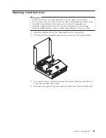
FRU
replacement
After
replacing
the
parts,
you
need
to
close
the
cover
and
reconnect
cables,
including
telephone
lines
and
power
cords.
Also,
depending
on
the
part
that
was
replaced,
you
might
need
to
confirm
the
updated
information
in
the
Setup
Utility
program.
See
″
Using
the
Setup
Utility
program
″
in
your
User
Guide
.
To
complete
the
part
installation:
1.
Ensure
that
all
components
have
been
reassembled
correctly
and
that
no
tools
or
loose
screws
are
left
inside
your
computer.
See“Locating
FRUs”
on
page
84
for
the
location
of
various
components.
2.
Make
sure
that
the
cables
are
routed
correctly
before
lowering
the
drive
bay
assembly.
Important
Correctly
route
all
power
supply
cables
to
avoid
interference
with
the
drive
bay
assembly.
Keep
cables
clear
of
the
hinges
and
sides
of
the
computer
chassis.
3.
Lower
the
drive
bay
assembly
and
position
the
drive
locks
to
the
locked
position.
Otherwise,
you
cannot
close
the
computer
cover.
4.
Close
the
computer
cover.
5.
If
a
cover
lock
is
installed,
lock
the
cover.
6.
Reconnect
the
external
cables
and
power
cords
to
the
computer.
See
“Locating
connectors
on
the
rear
of
your
computer”
on
page
82.
7.
If
you
are
replacing
the
system
board
or
microprocessor,
you
must
update
(flash)
the
BIOS.
See
“Updating
(flashing)
BIOS
from
a
diskette
or
CD-ROM”
on
page
115.
8.
To
update
your
configuration,
see
″
Using
the
Setup
Utility
program
″
in
the
User
Guide
.
Note:
In
most
areas
of
the
world,
Lenovo
requires
the
return
of
the
defective
CRU.
Information
about
this
will
come
with
the
CRU
or
will
come
a
few
days
after
the
CRU
arrives.
114
Hardware
Maintenance
Manual
Summary of Contents for ThinkCentre A55
Page 1: ...Hardware Maintenance Manual Types 9636 9638 9640 9641 9642 9643 9644 9645 ...
Page 2: ......
Page 3: ...Hardware Maintenance Manual ...
Page 16: ...10 Hardware Maintenance Manual ...
Page 17: ...Chapter 2 Safety information 11 ...
Page 18: ... 18 kg 37 lbs 32 kg 70 5 lbs 55 kg 121 2 lbs 1 2 12 Hardware Maintenance Manual ...
Page 22: ...16 Hardware Maintenance Manual ...
Page 23: ...1 2 Chapter 2 Safety information 17 ...
Page 24: ...18 Hardware Maintenance Manual ...
Page 25: ...1 2 Chapter 2 Safety information 19 ...
Page 32: ...26 Hardware Maintenance Manual ...
Page 33: ...Chapter 2 Safety information 27 ...
Page 34: ...1 2 28 Hardware Maintenance Manual ...
Page 38: ...32 Hardware Maintenance Manual ...
Page 39: ...1 2 Chapter 2 Safety information 33 ...
Page 54: ...48 Hardware Maintenance Manual ...
Page 102: ...96 Hardware Maintenance Manual ...
Page 115: ...Chapter 8 Replacing FRUs 109 ...
Page 122: ...116 Hardware Maintenance Manual ...
Page 206: ...200 Hardware Maintenance Manual ...
Page 209: ......
Page 210: ...Part Number 42Y4652 Printed in USA 1P P N 42Y4652 ...


