background image

Hardware Maintenance Manual

Machine Types: 3425, 3980, 5214, and 5354

Summary of Contents for ThinkCentre A58e

Page 1: ...Hardware Maintenance Manual Machine Types 3425 3980 5214 and 5354 ...

Page 2: ......

Page 3: ...Hardware Maintenance Manual Machine Types 3425 3980 5214 and 5354 ...

Page 4: ...101 Third Edition December 2010 Copyright Lenovo 2009 2010 LENOVO products data computer software and services have been developed exclusively at private expense and are sold to governmental entities as commercial items as defined by 48 C F R 2 101 with limited and restricted rights to use reproduction and disclosure LIMITED AND RESTRICTED RIGHTS NOTICE If products data computer software or servic...

Page 5: ...er Password 42 Change Supervisor Password 42 Setting changing and deleting a password 42 Enabling or disabling a device 42 Selecting a startup device 43 Selecting a temporary startup device 43 Selecting or changing the startup device sequence 43 Exiting from the Setup Utility program 43 Chapter 7 Symptom to FRU index 45 Hard disk drive boot error 45 Diagnostic error codes 45 Beep symptoms 61 POST ...

Page 6: ... a disc 99 Recovering from a POST BIOS update failure 100 Power management 100 Automatic configuration and power interface ACPI BIOS 100 Automatic Power On features 100 Appendix A Notices 101 Television output notice 102 Trademarks 102 iv Hardware Maintenance Manual ...

Page 7: ...vom Typ ACHTUNG oder VORSICHT in dieser Dokumentation bevor Sie irgendwelche Vorgänge durchführen Leggere le istruzioni introdotte da ATTENZIONE e PERICOLO presenti nel manuale prima di eseguire una qualsiasi delle istruzioni Certifique se de ler todas as instruções de cuidado e perigo neste manual antes de executar qualquer uma das instruções Es importante que lea todas las declaraciones de preca...

Page 8: ...e FRU part numbers Before or after June 2006 failed RoHS compliant parts must always be replaced using RoHS compliant FRUs so only the FRUs identified as compliant in the system hardware maintenance manual manor direct substitutions for those FRUs can be used Products marketed before June 2006 Products marketed after June 2006 Current or original part Replacement FRU Current or original part Repla...

Page 9: ...r people will not trip over it Do not wear loose clothing that can be trapped in the moving parts of a machine Ensure that your sleeves are fastened or rolled up above your elbows If your hair is long fasten it Insert the ends of your necktie or scarf inside clothing or fasten it with a nonconductive clip approximately 8 centimeters 3 inches from the end Do not wear jewelry chains metal frame eyeg...

Page 10: ...er There must be a complete circuit to cause an electric shock By observing the above rule you may prevent a current from passing through your body When using a tester set the controls correctly and use the approved probe leads and accessories for that tester Stand on suitable rubber mats obtained locally if necessary to insulate you from grounds such as metal floor strips and machine frames Obser...

Page 11: ...inspection guide The intent of this inspection guide is to assist you in identifying potentially unsafe conditions on these products Each machine as it was designed and built had required safety items installed to protect users and service personnel from injury This guide addresses only those items However good judgment should be used to identify potential safety hazards due to attachment of featu...

Page 12: ...rt Wear a grounded wrist strap against your skin to eliminate static on your body Prevent the part from touching your clothing Most clothing is insulative and retains a charge even when you are wearing a wrist strap Use the black side of a grounded work mat to provide a static free work surface The mat is especially useful when handling ESD sensitive devices Select a grounding system such as those...

Page 13: ...edures Connect and disconnect cables as described in the following tables when installing moving or opening covers on this product or attached devices To Connect To Disconnect 1 Turn everything OFF 2 First attach all cables to devices 3 Attach signal cables to connectors 4 Attach power cords to outlet 5 Turn device ON 1 Turn everything OFF 2 First remove power cords from outlet 3 Remove signal cab...

Page 14: ... products contain an embedded Class 3A or Class 3B laser diode Note the following Laser radiation when open Do not stare into the beam do not view directly with optical instruments and avoid direct exposure to the beam 18 kg 37 lbs 32 kg 70 5 lbs 55 kg 121 2 lbs CAUTION Use safe practices when lifting CAUTION The power control button on the device and the power switch on the power supply do not tu...

Page 15: ...Chapter 2 Safety information 9 ...

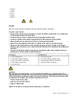
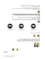
Page 16: ... 18 kg 37 lbs 32 kg 70 5 lbs 55 kg 121 2 lbs 1 2 PERIGO 10 Hardware Maintenance Manual ...

Page 17: ... ou abrir tampas deste produto ou de dispositivos conectados Para Conectar Para Desconectar 1 DESLIGUE Tudo 2 Primeiramente conecte todos os cabos aos dispositivos 3 Conecte os cabos de sinal aos conectores 4 Conecte os cabos de alimentação às tomadas 5 LIGUE os dispositivos 1 DESLIGUE Tudo 2 Primeiramente remova os cabos de alimentação das tomadas 3 Remova os cabos de sinal dos conectores 4 Remov...

Page 18: ... Radiação a laser quando aberto Não olhe diretamente para o feixe a olho nu ou com instrumentos ópticos e evite exposição direta ao feixe 18 kg 37 lbs 32 kg 70 5 lbs 55 kg 121 2 lbs CUIDADO Utilize procedimentos de segurança para levantar equipamentos CUIDADO O botão de controle de alimentação do dispositivo e o botão para ligar desligar da fonte de alimentação não desligam a corrente elétrica for...

Page 19: ...Chapter 2 Safety information 13 ...

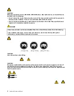
Page 20: ...1 2 14 Hardware Maintenance Manual ...

Page 21: ...Chapter 2 Safety information 15 ...

Page 22: ...e n utilisez qu une seule main pour connecter ou déconnecter les câbles d interface Ne mettez jamais un équipement sous tension en cas d incendie ou d inondation ou en présence de dommages matériels Avant de retirer les carters de l unité mettez celle ci hors tension et déconnectez ses cordons d alimentation ainsi que les câbles qui la relient aux réseaux aux systèmes de télécommunication et aux m...

Page 23: ...inappropriée Ne pas la jeter à l eau l exposer à des températures supérieures à 100 C chercher à la réparer ou à la démonter Ne pas mettre la pile à la poubelle Pour la mise au rebut se reporter à la réglementation en vigueur ATTENTION Si des produits à laser tels que des unités de CD ROM de DVD ROM des unités à fibres optiques ou des émetteurs sont installés prenez connaissance des informations s...

Page 24: ...annungen anliegen Aus Sicherheitsgründen Bei Gewitter an diesem Gerät keine Kabel anschließen oder lösen Ferner keine Installations Wartungs oder Rekonfigurationsarbeiten durchführen Gerät nur an eine Schutzkontaktsteckdose mit ordnungsgemäß geerdetem Schutzkontakt anschließen Alle angeschlossenen Geräte ebenfalls an Schutzkontaktsteckdosen mit ordnungsgemäß geerdetem Schutzkontakt anschließen Die...

Page 25: ...hiumbatterie nur durch eine Batterie mit der Teilenummer 45C1566 oder eine gleichwertige vom Hersteller empfohlene Batterie ersetzen Enthält das System ein Modul mit einer Lithiumbatterie dieses nur durch ein Modul desselben Typs und von demselben Hersteller ersetzen Die Batterie enthält Lithium und kann bei unsachgemäßer Verwendung Handhabung oder Entsorgung explodieren Die Batterie nicht mit Was...

Page 26: ...ichtlinien beim Anheben der Maschine beachten ACHTUNG Mit dem Netzschalter an der Einheit und am Netzteil wird die Stromversorgung für die Einheit nicht unterbrochen Die Einheit kann auch mit mehreren Netzkabeln ausgestattet sein Um die Stromversorgung für die Einheit vollständig zu unterbrechen müssen alle zum Gerät führenden Netzkabel vom Netz getrennt werden 1 2 20 Hardware Maintenance Manual ...

Page 27: ...Chapter 2 Safety information 21 ...

Page 28: ...o scollegare qualsiasi cavo oppure effettuare l installazione la manutenzione o la riconfigurazione del prodotto durante un temporale Collegare tutti i fili elettrici a una presa di alimentazione correttamente cablata e dotata di messa a terra Collegare alle prese elettriche appropriate tutte le apparecchiature che verranno utilizzate per questo prodotto 22 Hardware Maintenance Manual ...

Page 29: ...ndo si sostituisce la batteria al litio utilizzare solo il Numero parte 45C1566 o un tipo di batteria equivalente consigliato dal produttore Se sul sistema è presente un modulo che contiene una batteria al litio sostituirlo solo con un tipo di modulo dello stesso tipo della stessa casa di produzione La batteria contiene litio e può esplodere se usata maneggiata o smaltita in modo non corretto Non ...

Page 30: ...5 lbs 55 kg 121 2 lbs ATTENZIONE Prestare attenzione nel sollevare l apparecchiatura ATTENZIONE Il pulsante di controllo dell alimentazione presente sull unità e l interruttore dell alimentatore non disattivano l alimentazione corrente fornita all unità E possibile che l unità disponga di più cavi di alimentazione Per disattivare l alimentazione dall unità accertarsi che tutti i cavi di alimentazi...

Page 31: ...Chapter 2 Safety information 25 ...

Page 32: ...n de este producto durante una tormenta eléctrica Conecte todos los cables de alimentación a tomas de corriente debidamente cableadas y conectadas a tierra Cualquier equipo que se conecte a este producto también debe conectarse a tomas de corriente debidamente cableadas Siempre que sea posible utilice una sola mano para conectar o desconectar los cables de señal No encienda nunca un equipo cuando ...

Page 33: ...ya una batería de litio utilice solamente una batería número de pieza 45C1566 u otra de tipo equivalente recomendada por el fabricante Si su sistema dispone de un módulo que contiene una batería de litio reemplácelo sólo con el mismo tipo de módulo del mismo fabricante La batería contiene litio y puede explotar si no se utiliza manipula o desecha correctamente No debe Arrojarla al agua o sumergirl...

Page 34: ... 2 lbs PRECAUCIÓN Adopte procedimientos seguros al levantar el equipo PRECAUCIÓN El botón de control de alimentación del dispositivo y el interruptor de alimentación de la fuente de alimentación no desconectan la corriente eléctrica suministrada al dispositivo Además el dispositivo podría tener más de un cable de alimentación Para suprimir toda la corriente eléctrica del dispositivo asegúrese de q...

Page 35: ...ages on the Lenovo Support Web site at http www lenovo com support 3 If you want to install a different language version of the Adobe Reader program rather than the version preinstalled on your computer download the language version you want from the Adobe Web site at http www adobe com Lenovo ThinkVantage Tools The Lenovo ThinkVantage Tools program guides you to a host of information sources and ...

Page 36: ...system on Windows 7 click Start Help and Support Lenovo Access Help To open the Access Help information system on Windows Vista or Windows XP click Start All Programs ThinkVantage Access Help After you have opened the Access Help information system use the left panel to make a selection from the Contents tab or the Index tab or use the Search tab to find a particular word or phrase Additional info...

Page 37: ...g 10 to 60 C 14 to 140 F without package Humidity Operating 20 to 80 10 per hour non condensing Non operating 20 to 90 10 per hour non condensing Maximum altitude Operating 50 to 10 000 ft 15 2 to 3 048 m Non operating 50 to 35 000 ft 15 2 to 10 668 m Electrical input Input voltage Low range Minimum 100 V ac Maximum 127 V ac Input frequency range 50 to 60 Hz High range Minimum 200 V ac Maximum 240...

Page 38: ...32 Hardware Maintenance Manual ...

Page 39: ...error codes Listen for the beep codes Look for readable instructions or a main menu on the display If you do not receive the correct response proceed to step 5 on page 33 If you do receive the correct response run the diagnostics See Running the diagnostic program from a diagnostic disc on page 38 5 Check the following conditions and follow the instructions If you hear beep codes during power on s...

Page 40: ...em determination If possible have this information available when requesting assistance from Service Support and Engineering functions Machine type and model Microprocessor or hard disk drive upgrades Failure symptom Do diagnostics indicate a failure What when where single or multiple systems Is the failure repeatable Has this configuration ever worked If it has been working what changes were made...

Page 41: ...Comparing the configuration and software setup between working and non working systems will often lead to problem resolution Chapter 4 General checkout 35 ...

Page 42: ...36 Hardware Maintenance Manual ...

Page 43: ... Lenovo and get more information about your computer You can use the Diagnostics feature of the Lenovo ThinkVantage Toolbox program to test devices diagnose problems create bootable diagnostic media update system drivers and review system information To diagnose the computer problems by using the Lenovo ThinkVantage Toolbox program click Start All Programs Lenovo ThinkVantage Tools System Health a...

Page 44: ...ing and using rescue media in your ThinkCentre User Guide PC Doctor for DOS You can also download the latest version of the PC Doctor for DOS diagnostic program from http www lenovo com support The PC Doctor for DOS diagnostic program runs independently of the Windows operating system Use the PC Doctor for DOS diagnostic program if you are unable to start the Windows operating system or if the two...

Page 45: ... in all categories From within a test category press Ctrl Enter to automatically run only the selected tests in that category Using the cursor movement keys highlight a single test within a test category and then press Enter This runs only that test Press Esc at any time to stop the testing process Test results N A PASSED FAILED ABORTED are displayed in the field beside the test description and in...

Page 46: ... Erase Hard Drive provides a DOS utility that performs the following Performs all the steps in Quick Erase Provides a DOS utility that writes random data to all sectors of the hard disk drive Provides an estimate of time to completion along with a visual representation of completion status Provides messages that warn the user about a non recoverable process Important Make sure that all data is bac...

Page 47: ...uctions on the screen When working with the Setup Utility program you must use the keyboard The keys used to perform various tasks are displayed at the bottom of each screen Using passwords By using the Setup Utility program you can set passwords to prevent unauthorized access to your computer and data The following options are available for you to set a user password or a supervisor password Set ...

Page 48: ...t the Setup Utility program See Starting the Setup Utility program on page 41 2 From the Setup Utility program main menu select Security 3 Follow the instructions displayed on the screen to set change or delete a password Note A password can be any combination of seven to ten alphabetic and numeric characters For more information see Password considerations on page 41 Enabling or disabling a devic...

Page 49: ...ary Boot Sequence Read the information displayed on the right side of the screen 3 Select the first boot device second boot device and so on 4 Press Esc to return to the Startup menu Then select the devices for the Automatic Boot Sequence and Error Boot Sequence 5 Press Esc to return to the Setup Utility program main menu You might have to press Esc several times 6 Press F10 to save and exit the S...

Page 50: ...44 Hardware Maintenance Manual ...

Page 51: ... configuration Check the configuration and ensure the start up drive is in the boot sequence No operating system installed on the boot drive Install an operating system on the boot drive The boot sector on the start up drive is corrupted The drive must be formatted Do the following 1 Attempt to back up the data on the failing hard disk drive 2 Using the operating system programs format the hard di...

Page 52: ...IOS DMI data error 1 Flash the system See Updating flashing BIOS from a disc on page 99 2 System board 000 195 XXX BIOS Test aborted by user Information only Re start the test if necessary 000 196 XXX BIOS test halt error threshold exceeded 1 Press F3 to review the log file 2 Re start the test to reset the log file 000 197 XXX BIOS test warning 1 Make sure the component that is called out is conne...

Page 53: ...m a disc on page 99 3 System board 001 032 XXX System device controller failure System board 001 034 XXX System device buffer allocation failure 1 Reboot the system 2 Flash the system See Updating flashing BIOS from a disc on page 99 3 Run memory test 4 System board 001 035 XXX System device reset condition detected System board 001 036 XXX System register error System board 001 038 XXX System ext...

Page 54: ...0 XXX System ECC error System board 001 254 XXX 001 255 XXX 001 256 XXX 001 257 XXX System DMA error System board 001 260 XXX 001 264 XXX System IRQ error System board 001 268 XXX System IRQ1 failure 1 Device on IRQ1 2 System board 001 269 XXX System IRQ2 failure 1 Device on IRQ2 2 System board 001 270 XXX System IRQ3 failure 1 Device on IRQ3 2 System board 001 271 XXX System IRQ4 failure 1 Device...

Page 55: ...rd 001 299 XXX System RTC periodic interrupt failure System board 001 300 XXX System RTC Alarm failure System board 001 301 XXX System RTC Century byte error 1 Flash the system See Updating flashing BIOS from a disc on page 99 2 System board 005 000 XXX Video test passed No action 005 00X XXX Video error 1 Video card if installed 2 System board 005 010 XXX 005 011 XXX 005 012 XXX 005 013 XXX Video...

Page 56: ...ent called out in warning statement 4 Replace the component under test 005 198 XXX Video test aborted 1 If a component is called out make sure it is connected and or enabled See Chapter 6 Using the Setup Utility on page 41 2 Flash the system and re test See Updating flashing BIOS from a disc on page 99 3 Go to Undetermined problems on page 64 005 199 XXX Video test failed cause unknown 1 Go to Und...

Page 57: ...15 002 XXX USB port timeout 1 Remove USB device s and re test 2 System board 015 015 XXX USB port external loopback failure 1 Remove USB device s and re test 2 System board 015 027 XXX USB port configuration setup error 1 Flash the system See Updating flashing BIOS from a disc on page 99 2 System board 015 032 XXX USB port device controller failure System board 015 034 XXX USB port buffer allocati...

Page 58: ...borted by user 1 PCI card 2 Information only Re start the test if necessary 018 196 XXX PCI card test halt error threshold exceeded 1 Press F3 to review the log file 2 Re start the test to reset the log file 018 197 XXX PCI card test warning 1 Make sure the component that is called out is connected and or enabled See Chapter 6 Using the Setup Utility on page 41 2 Re run test 3 Replace the componen...

Page 59: ... on page 99 3 Go to Undetermined problems on page 64 020 199 XXX PCI test failed cause unknown 1 Go to Undetermined problems on page 64 2 Flash the system and re test See Updating flashing BIOS from a disc on page 99 3 Replace component under function test 020 262 XXXPCI system error 1 PCI card 2 Riser card if installed 3 System board 025 000 XXXIDE interface Test Passed No action 025 00X XXX 025 ...

Page 60: ...o Undetermined problems on page 64 2 Flash the system and re test See Updating flashing BIOS from a disc on page 99 3 Replace component under function test 030 000 XXX SCSI interface Test Passed No action 030 00X XXX 030 01X XXX SCSI interface failure 1 SCSI signal cable 2 Check AC DC power adapter 3 SCSI device 4 SCSI adapter card if installed 5 System board 030 027 XXX SCSI interface configurati...

Page 61: ...dapter card if installed 4 System board 035 195 XXX RAID interface test aborted by user Information only Re start the test if necessary 035 196 XXX RAID interface test halt error threshold exceeded 1 Press F3 to review the log file 2 Re start the test to reset the log file 035 197 XXX RAID interface test warning 1 Make sure the component that is called out is connected and or enabled See Chapter 6...

Page 62: ...4 Replace the component under test 071 198 XXX Audio port test aborted 1 If a component is called out make sure it is connected and or enabled See Chapter 6 Using the Setup Utility on page 41 2 Flash the system and re test See Updating flashing BIOS from a disc on page 99 3 Go to Undetermined problems on page 64 071 199 XXX Audio port test failed cause unknown 1 See Undetermined problems on page 6...

Page 63: ...e presence 1 Mouse 2 System board 086 032 XXX Mouse port interface device controller failure 1 Mouse 2 System board 086 035 XXX Mouse port interface Reset 1 Mouse 2 System board 086 040 XXX Mouse port interface IRQ failure 1 Run Setup 2 Mouse 3 System board 086 195 XXX Mouse port interface test aborted by user Information only Re start the test if necessary 086 196 XXX Mouse port interface test ha...

Page 64: ...o Undetermined problems on page 64 089 199 XXX Microprocessor test failed cause unknown 1 See Undetermined problems on page 64 2 Flash the system and re test See Updating flashing BIOS from a disc on page 99 3 Replace component under function test 170 000 XXX Voltage sensor s test passed No action 170 0XX XXX Voltage sensor s failure 1 Flash system 2 System board 170 195 XXX Voltage sensor s test ...

Page 65: ...t is called out is connected and or enabled See Chapter 6 Using the Setup Utility on page 41 2 Re run test 3 Replace the component that is called out in warning statement 4 Replace the component under test 175 198 XXX Thermal sensor s test aborted 1 If a component is called out make sure it is connected and or enabled 2 Flash the system and re test See Updating flashing BIOS from a disc on page 99...

Page 66: ...DE error 1 Hard Disk Drive Cable 2 Check AC DC power adapter voltages 3 Reseat the hard disk drive cable 4 Hard Disk drive IDE 5 System board 217 28X XXX 217 29X XXX Hard disk drive SCSI error 1 Hard Disk Drive Cable 2 Check AC DC power adapter voltages 3 Reseat the hard disk drive cable 4 Hard Disk drive SCSI 5 SCSI adapter card 6 System board 220 000 XXX Hi Capacity cartridge drive test passed N...

Page 67: ... Express card Modem card Media reader and retry If the problem persists replace the system board Otherwise reinstall the optional adapters one at a time until the failing adapter is determined 8 beeps Replace the system board POST error codes Each time you power on the system it performs a series of tests that check the operation of the system and some options This series of tests is called the Po...

Page 68: ...he computer without a keyboard set the error halt condition in Setup to HALT ON ALL BUT KEYBOARD The BIOS then ignores the missing keyboard during POST Memory test This message displays during a full memory test counting down the memory areas being tested Memory test fail If POST detects an error during memory testing additional information appears This information gives specifics about the type a...

Page 69: ...or does not light when drive is active 1 Diskette Drive 2 System Board 3 Diskette Drive Cable Flashing cursor with an otherwise blank display 1 System Board 2 Primary Hard Disk Drive 3 Hard Disk Drive Cable Incorrect memory size during POST 1 Run the Memory tests 2 Memory Module 3 System Board Insert a Diskette icon appears with a known good diagnostics diskette in the first 3 5 inch diskette driv...

Page 70: ...o not work 1 Keyboard 2 Keyboard Cable 3 System Board Undetermined problems If you encounter undetermined problems do the following 1 Turn off the computer and the power 2 Remove or disconnect the following components if installed one at a time a External devices modem printer or mouse b Memory modules c Extended video memory d External Cache e External Cache RAM f Hard disk drive 3 Turn on the po...

Page 71: ...ians Locations Locating connectors on the front of your computer Front connector locations shows the locations of the connectors on the front of your computer Figure 1 Front connector locations 1 USB connector 3 Headphone connector 2 Microphone connector 4 USB connector Locating connectors on the rear of your computer Rear connector locations shows the locations of the connectors on the rear of yo...

Page 72: ...A monitor connector 8 Audio line in connector 4 USB connectors 4 9 Serial port some models 5 Ethernet connector Locating components Figure 3 Component locations on page 67 shows the locations of the various components in your computer To remove the computer cover see Removing the computer cover on page 68 66 Hardware Maintenance Manual ...

Page 73: ...ard disk drive 7 System board 3 System fan assembly 8 Battery 4 Optical drive 9 Memory modules 2 5 Microprocessor Locating parts on the system board Figure 4 System board part locations on page 68 shows the locations of the parts on the system board Chapter 8 Replacing FRUs 67 ...

Page 74: ...oving the computer cover Attention Do not open your computer or attempt any repair before reading and understanding the Important safety information in the ThinkCentre Safety and Warranty Guide that came with your computer To obtain a copy of the ThinkCentre Safety and Warranty Guide go to http www lenovo com support This section provides instructions on how to remove the computer cover CAUTION Tu...

Page 75: ...nect all the cables from the system board and completely remove the computer cover Removing and reinstalling the front bezel Attention Do not open your computer or attempt any repair before reading and understanding the Important safety information in the ThinkCentre Safety and Warranty Guide that came with your computer To obtain a copy of the ThinkCentre Safety and Warranty Guide go to http www ...

Page 76: ...ry module Attention Do not open your computer or attempt any repair before reading and understanding the Important safety information in the ThinkCentre Safety and Warranty Guide that came with your computer To obtain a copy of the ThinkCentre Safety and Warranty Guide go to http www lenovo com support This section provides instructions on how to install or replace a memory module Your computer ha...

Page 77: ...gure 8 Removing the memory module 4 Insert the new memory module into the appropriate memory slot Make sure that the notch 2 of the new memory module are aligned with the slot key 1 of the memory slot Then press the new memory module firmly and pivot it down until it snaps into position Make sure that the new memory module is firmly installed in the memory slot and does not move easily Figure 9 In...

Page 78: ... error message is displayed when you turn on the computer Before performing the following procedure be sure to read and understand the information about replacing and disposing of the battery in the Lithium battery notice section of the ThinkCentre Safety and Warranty Guide To replace the battery do the following 1 Remove the computer cover See Removing the computer cover on page 68 2 Locate the b...

Page 79: ... prevent you from replacing the hard disk drive Disconnect the power cable from the optical drive first 3 Place your finger on the tab located on the front of the hard disk drive and push upward Meanwhile press inward on the side tabs of the bracket and pivot the hard disk drive upward to remove it from the hard disk drive bay Figure 12 Removing the hard disk drive 4 Disconnect the signal cable an...

Page 80: ...f hardware go to the appropriate section To complete the replacement go to Completing the parts replacement on page 84 Replacing the optical drive Attention Do not open your computer or attempt any repair before reading and understanding the Important safety information in the ThinkCentre Safety and Warranty Guide that came with your computer To obtain a copy of the ThinkCentre Safety and Warranty...

Page 81: ...he optical drive 4 Press the blue release button 1 and slide the optical drive out the front of the computer Figure 15 Removing the optical drive 5 Remove the optical drive retainer 1 from the old optical drive and install it on the side of the new optical drive Figure 16 Installing the retainer on the optical drive 6 Slide the new optical drive into the drive bay until it snaps into position Chap...

Page 82: ...vides instructions on how to replace the heat sink CAUTION The heat sink might be very hot Turn off the computer and wait three to five minutes to let the computer cool before removing the computer cover To replace the heat sink do the following 1 Remove the computer cover See Removing the computer cover on page 68 2 Locate the heat sink See Locating components on page 66 3 Remove the four screws ...

Page 83: ...y information in the ThinkCentre Safety and Warranty Guide that came with your computer To obtain a copy of the ThinkCentre Safety and Warranty Guide go to http www lenovo com support This section provides instructions on how to replace the system fan assembly To replace the system fan assembly do the following 1 Remove the computer cover See Removing the computer cover on page 68 2 Disconnect the...

Page 84: ... long rubber mounts by pushing them through the holes on the rear of the chassis If necessary pull the rubber mounts through the holes from the inside of the chassis to make sure that the rubber mounts are installed in place 7 To install the new system fan assembly into the chassis align the holes on the new system fan assembly with the long rubber mounts in the chassis Then push or pull the rubbe...

Page 85: ... http www lenovo com support This section provides instructions on how to replace the microprocessor CAUTION The heat sink and microprocessor might be very hot Turn off the computer and wait three to five minutes to let the computer cool before removing the computer cover To replace the microprocessor do the following 1 Remove the computer cover See Removing the computer cover on page 68 2 Remove ...

Page 86: ... can either look for the small triangle 1 on one corner of the microprocessor or note the orientation of the notches 2 on the microprocessor This is important when installing the new microprocessor on the system board c Touch only the sides of the microprocessor Do not touch the gold contacts on the bottom d Do not drop anything onto the microprocessor socket while it is exposed The socket pins mu...

Page 87: ... beveled corner of the microprocessor socket 10 Lower the new microprocessor straight down into the microprocessor socket on the system board 11 Close the microprocessor retainer and lock it into position with the small handle to secure the new microprocessor in the socket 12 Reinstall the heat sink on the system board See Replacing the heat sink on page 76 13 Reinstall any other parts and reconne...

Page 88: ...the old system board See Replacing the heat sink on page 76 6 Remove the microprocessor from the old system board See Replacing the microprocessor on page 79 7 Remove the screws that secure the old system board Then carefully remove the old system board out of the chassis 8 Place the old system board on a clean and flat surface 9 Position the new system board so that the screw holes are aligned wi...

Page 89: ...y of the ThinkCentre Safety and Warranty Guide go to http www lenovo com support This section provides instructions on how to replace the ac power adapter To replace the ac power adapter do the following 1 Remove any media from the drives Then turn off all attached devices and the computer 2 Disconnect the ac power adapter cord from the electrical outlet 3 Locate the ac power adapter connector on ...

Page 90: ...in the Setup Utility program Refer to Chapter 6 Using the Setup Utility on page 41 To reinstall the computer cover and reconnect cables to your computer do the following 1 Make sure that all components have been reassembled correctly and that no tools or loose screws are left inside your computer See Locating components on page 66 for the locations of the various components in your computer 2 If y...

Page 91: ...he computer cover on the chassis so that the rail guide on the computer cover engages the rail on the chassis Then pivot the computer cover closed until it snaps into position Figure 28 Installing the computer cover Chapter 8 Replacing FRUs 85 ...

Page 92: ... to the computer 7 To update your configuration refer to Chapter 6 Using the Setup Utility on page 41 Note In most areas of the world Lenovo requires the return of the defective CRUs Information about this will come with the CRUs or will come a few days after you received the CRUs 86 Hardware Maintenance Manual ...

Page 93: ...tional service CRU Machine Type 3425 Item 3425 FRUs FRU CRU 1 Hard disk drive SATA 160GB 7200RPM 3Gb 8M models A1J A2J A5J A6J A9J B1J 40Y9035 1 1 Hard disk drive SATA 160GB 7200RPM 3Gb 8M models A1J A2J A5J A6J A9J B1J 53Y6837 1 1 Hard disk drive SATA 250GB 7200RPM 3Gb 8M models A3J A4J A7J A8J 40Y9036 1 1 Hard disk drive SATA 250GB 7200RPM 3Gb 8M models A3J A4J A7J A8J 45K0408 1 1 Hard disk driv...

Page 94: ...Hz R 0 Stepping 45nm 1066MHz FSB 2MB L2 models 71Y6128 N 5 Microprocessor Wolfdale Core2 Duo E7400 45W 2 80GHz R 0 stepping 1066MHz FSB 3MB L2 models A3J A4J A7J A8J 71Y6421 N 5 Microprocessor Wolfdale Core2 Duo E7600 45W 3 06GHz 1066MHz FSB R 0 stepping 3MB L2 models 71Y6423 N 5 Microprocessor Wolfdale Core2 Duo E8400 3 0G 1333 6M 775 QHFH E0 45W 3 00GHz E 0 Stepping 45nm 1333MHz FSB 6MB L2 model...

Page 95: ...rds Primary FRU CRU Line Cord Japanese and Japanese English models A1J A2J A3J A4J A5J A6J A7J A8J A9J B1J 42T5011 1 3425 Power Cords Secondary FRU CRU Line Cord Japanese and Japanese English models A1J A2J A3J A4J A5J A6J A7J A8J A9J B1J 42T5096 1 3425 Windows XP Pro Recovery CDs FRU CRU Japanese models 71Y7112 1 3425 Vista Home Basic 32 Recovery DVDs FRU CRU Japanese models 71Y7120 1 3425 Vista ...

Page 96: ...SATA 320GB 7200RPM 3Gb 8M models 87H4891 1 1 Hard disk drive SATA 320GB 7200RPM 3Gb 8M models 45K0409 1 1 Hard disk drive SATA 500GB 7200RPM 3Gb 16M models 41X5582 1 1 Hard disk drive SATA 500GB 7200RPM 3Gb 16M models 45K0410 1 3 Optical drive DVD ROM Drive 16x 48x SATA models 41N3325 1 3 Optical drive DVD ROM Drive 16x 48x SATA models 71Y5543 1 3 Optical drive DVD Recordable Rambo 8 SATA 12XRAM W...

Page 97: ...5 Microprocessor Wolfdale Core2 Duo E8500 3 16G 1333 6M 775 QHFG E0 45W 3 16GHz E 0 Stepping 45nm 1333MHz FSB 6MB L2 models 71Y6129 N 7 System board E G31 G mITX H Planar G31_ALC662_8111C non AMT models 71Y6072 N 9 Memory module Hyn_R HY5PS1G831C 1GB PC2 5300 DDRII 667MHz models 71Y6091 1 9 Memory module Hyn_R H5PS1G83EFR Y5C 2GB PC2 5300 667MHz DDR2 SDRAM models CTO 71Y8469 1 The FRUs listed in t...

Page 98: ... 3980 Vista Home Basic 32 Recovery DVDs FRU CRU Japanese models 71Y7120 1 3980 Vista Business 32 Recovery DVDs FRU CRU Japanese models 71Y7116 1 3980 Vista Ultimate 32 64 Recovery DVDs FRU CRU Japanese models 71Y7121 1 3980 Vista Home Premium 32 64 Recovery DVDs FRU CRU Japanese models 71Y7119 1 3980 Windows 7 Home Premium 32 Recovery DVDs FRU CRU Japanese models 71Y8192 1 3980 Windows 7 Professio...

Page 99: ...sk drive SATA 500GB 7200RPM 3Gb 16M models 41X5582 1 1 Hard disk drive SATA 500GB 7200RPM 3Gb 16M models 45K0410 1 3 Optical drive DVD ROM Drive 16x 48x SATA models A1J A3J A5J B1J B3J 41N3325 1 3 Optical drive DVD ROM Drive 16x 48x SATA models A1J A3J A5J B1J B3J 71Y5543 1 3 Optical drive DVD Recordable Rambo 8 SATA 12XRAM Write models A2J A4J A6J B2J B4J 43C1042 1 3 Optical drive DVD Recordable ...

Page 100: ...MHz FSB 6MB L2 models 71Y6129 N 7 System board E G31 G mITX H Planar G31_ALC662_8111C non AMT models A1J A2J A3J A4J A5J A6J B1J B2J B3J B4J 71Y6072 N 9 Memory module Hyn_R H5PS1G83EFR Y5C 2GB PC2 5300 667MHz DDR2 SDRAM models CTO B1J B2J B3J B4J 71Y8469 1 9 Memory module Hyn_R HY5PS1G831C 1GB PC2 5300 DDRII 667MHz models A1J A2J A3J A4J A5J A6J 71Y6091 1 The FRUs listed in the following tables ar...

Page 101: ...14 Windows XP Pro Recovery CDs FRU CRU Japanese models 71Y7112 1 5214 Vista Home Basic 32 Recovery DVDs FRU CRU Japanese models 71Y7120 1 5214 Vista Business 32 Recovery DVDs FRU CRU Japanese models A1J A2J A3J A4J A5J A6J 71Y7116 1 5214 Vista Ultimate 32 64 Recovery DVDs FRU CRU Japanese models 71Y7121 1 5214 Vista Home Premium 32 64 Recovery DVDs FRU CRU Japanese models 71Y7119 1 5214 Windows 7 ...

Page 102: ...disk drive SATA 500GB 7200RPM 3Gb 16M models 45K0410 1 3 Optical drive DVD ROM Drive 16x 48x SATA models A1J A3J A5J 41N3325 1 3 Optical drive DVD ROM Drive 16x 48x SATA models A1J A3J A5J 71Y5543 1 3 Optical drive DVD Recordable Rambo 8 SATA 12XRAM Write models A2J A4J A6J 43C1042 1 3 Optical drive DVD Recordable Rambo 8 SATA 12XRAM Write models A2J A4J A6J 71Y5545 1 4 Power supply 120W ac dc pow...

Page 103: ...rd E G31 G mITX H Planar G31_ALC662_8111C non AMT models A1J A2J A3J A4J A5J A6J 71Y6072 N 9 Memory module Hyn_R H5PS1G83EFR Y5C 2GB PC2 5300 667MHz DDR2 SDRAM models CTO 71Y8469 1 9 Memory module Hyn_R HY5PS1G831C 1GB PC2 5300 DDRII 667MHz models A1J A2J A3J A4J A5J A6J 71Y6091 1 The FRUs listed in the following tables are not illustrated 5354 FRUs FRU CRU Front bezel assembly all models 45K6161 ...

Page 104: ...Ds FRU CRU Japanese models 71Y7112 1 5354 Vista Home Basic 32 Recovery DVDs FRU CRU Japanese models 71Y7120 1 5354 Vista Business 32 Recovery DVDs FRU CRU Japanese models A1J A2J A3J A4J A5J A6J 71Y7116 1 5354 Vista Ultimate 32 64 Recovery DVDs FRU CRU Japanese models 71Y7121 1 5354 Vista Home Premium 32 64 Recovery DVDs FRU CRU Japanese models 71Y7119 1 5354 Windows 7 Home Premium 32 Recovery DVD...

Page 105: ... on page 99 BIOS levels An incorrect level of BIOS can cause false errors and unnecessary FRU replacement Use the following information to determine the current level of BIOS installed in the computer the latest BIOS available for the computer and where to obtain the latest level of BIOS To determine the current level of BIOS Start the Setup Utility program See Starting the Setup Utility program o...

Page 106: ...will automatically begin recovering the POST BIOS and you will see a screen indicating that the recovery has started After the recovery session completes the computer restarts automatically 5 Remove the POST BIOS update flash update disc from the optical drive Power management Power management reduces the power consumption of certain components of the computer such as the system power supply proce...

Page 107: ...ublication Lenovo may make improvements and or changes in the product s and or the program s described in this publication at any time without notice The products described in this document are not intended for use in implantation or other life support applications where malfunction may result in injury or death to persons The information contained in this document does not affect or change Lenovo...

Page 108: ...ended for home and other limited viewing uses only unless otherwise authorized by Macrovision Corporation Reverse engineering or disassembly is prohibited Trademarks The following terms are trademarks of Lenovo in the United States other countries or both Lenovo Rescue and Recovery The Lenovo logo ThinkCentre ThinkVantage Celeron Intel and Intel Core are trademarks of Intel Corporation in the Unit...

Page 109: ......

Page 110: ...Part Number 71Y6308 Printed in USA 1P P N 71Y6308 71Y6308 ...

Reviews: