

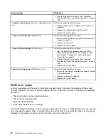


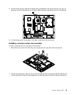
1
System board shielding
10
Internal speaker
2
Integrated webcam
11
Front bezel
3
Heat sink assembly
12
Internal speaker
4
Microprocessor fan assembly
13
Rear I/O assembly
5
Power supply assembly
14
Rear I/O shielding
6
Hard disk drive
15
Power connector bracket
7
Optical drive
16
Power supply assembly cage
8
Main bracket
17
System board
9
LCD panel
18
Microprocessor
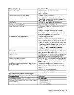
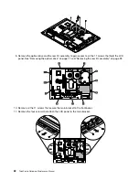
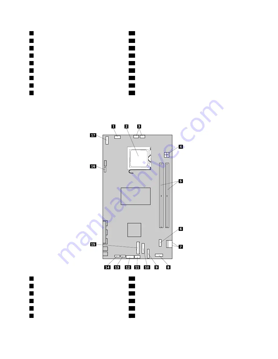
System board connectors
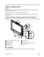
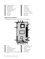
The following illustration shows the locations of the system board connectors.
1
Inverter
10
Rear USB assembly - 40 pin
2
Microprocessor
11
Internal USB assembly
3
Microprocessor fan assembly
12
Debug pin
4
Power supply assembly
13
Power switch assembly
5
Memory modules (2)
14
Internal speakers
6
Power cables for hard disk drive and optical
drive
15
Mini PCI Express
68
ThinkCentre Hardware Maintenance Manual
Summary of Contents for ThinkCentre A70z ALL-IN-ONE
Page 1: ...ThinkCentre Hardware Maintenance Manual Machine Types 0401 0421 0994 1165 1184 1186 and 2565 ...
Page 2: ......
Page 3: ...ThinkCentre Hardware Maintenance Manual Machine Types 0401 0421 0994 1165 1184 1186 and 2565 ...
Page 15: ...Chapter 2 Safety information 9 ...
Page 19: ...Chapter 2 Safety information 13 ...
Page 20: ...1 2 14 ThinkCentre Hardware Maintenance Manual ...
Page 21: ...Chapter 2 Safety information 15 ...
Page 27: ...Chapter 2 Safety information 21 ...
Page 31: ...Chapter 2 Safety information 25 ...
Page 46: ...40 ThinkCentre Hardware Maintenance Manual ...
Page 188: ...182 ThinkCentre Hardware Maintenance Manual ...
Page 192: ...186 ThinkCentre Hardware Maintenance Manual ...
Page 193: ......
Page 194: ...Part Number 71Y7087 Printed in USA 1P P N 71Y7087 71Y7087 ...


