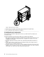
Figure 41. Removing the front bezel
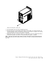
4. To reinstall the front bezel, align the other three plastic tabs on the bottom of the front bezel with the
corresponding holes in the chassis, then pivot the front bezel inward until it snaps into position.
Figure 42. Reinstalling the front bezel
5. Go to “Completing the parts replacement” on page 129.
Accessing the system board components and drives
Attention
Do not open your computer or attempt any repair before reading and understanding the “Important safety information”
in the
ThinkCentre Safety and Warranty Guide
that came with your computer. To obtain a copy of the
ThinkCentre
Safety and Warranty Guide
, go to:
http://www.lenovo.com/support
This section provides instructions on how to access the system board components and drives.
Chapter 9
.
Replacing FRUs (Machine Types: 0804, 0809, 0811, 0822, 0825, 0828, 0830, 0833,
0837, 0843, 0845, 0847, and 0849.)
103
Summary of Contents for ThinkCentre M70e
Page 2: ......
Page 8: ...vi ThinkCentre Hardware Maintenance Manual ...
Page 17: ...Chapter 2 Safety information 9 ...
Page 21: ...Chapter 2 Safety information 13 ...
Page 22: ...1 2 14 ThinkCentre Hardware Maintenance Manual ...
Page 23: ...Chapter 2 Safety information 15 ...
Page 29: ...Chapter 2 Safety information 21 ...
Page 33: ...Chapter 2 Safety information 25 ...
Page 40: ...32 ThinkCentre Hardware Maintenance Manual ...
Page 74: ...66 ThinkCentre Hardware Maintenance Manual ...
Page 104: ...96 ThinkCentre Hardware Maintenance Manual ...
Page 402: ...394 ThinkCentre Hardware Maintenance Manual ...
Page 407: ......
Page 408: ...Part Number 71Y8558 Printed in USA 1P P N 71Y8558 71Y8558 ...


