Figure 60. Removing the heat sink fan duct
5. Disconnect the power supply assembly cables from all drives and from the 24-pin power connector and
4-pin power connector on the system board. See “Locating parts on the system board” on page 99.
Note:
You might also need to release the power supply assembly cables from some cable clips or ties
that secure the cables to the chassis. Make sure that you note the cable routing before disconnecting
the cables.
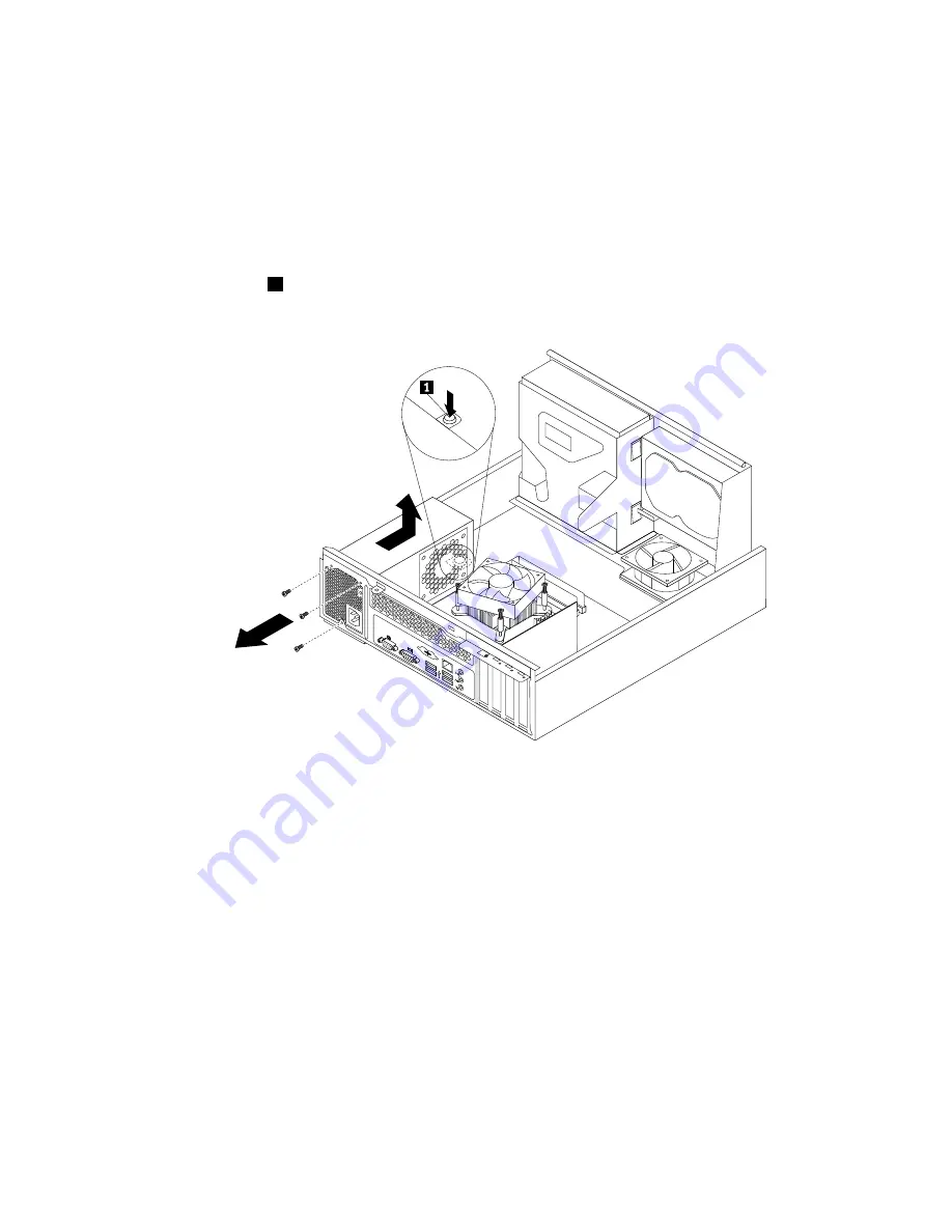
6. At the rear of the computer, remove the three screws that secure the power supply assembly. Press the
power supply clip
1
downward to release the power supply assembly and then slide the power supply
assembly to the front of the computer. Lift the power supply assembly out of the computer.
Figure 61. Removing the power supply assembly
7. Make sure that the new power supply assembly is the correct replacement. Some power supply
assemblies automatically sense the voltage or accept universal input, some power supply assemblies
are voltage specific, and some power supply assemblies have a voltage-selection switch. If your power
supply assembly has a voltage-selection switch, make sure that you set the voltage-selection switch
to match the voltage available at your electrical outlet. If necessary, use a ballpoint pen to slide the
voltage-selection switch to the correct position.
• If the voltage supply range in your local country or region is 100–127 V ac, set the voltage-selection
switch to 115 V.
• If the voltage supply range in your local country or region is 200–240 V ac, set the voltage-selection
switch to 230 V.
8. Install the new power supply assembly into the chassis so that the screw holes in the new power supply
assembly are aligned with the corresponding holes in the rear of the chassis. Then, install the three
screws to secure the new power supply assembly in place.
Note:
Use only screws provided by Lenovo.
Chapter 9
.
Replacing FRUs (Machine Types: 0804, 0809, 0811, 0822, 0825, 0828, 0830, 0833,
0837, 0843, 0845, 0847, and 0849.)
119
Summary of Contents for ThinkCentre M70e
Page 2: ......
Page 8: ...vi ThinkCentre Hardware Maintenance Manual ...
Page 17: ...Chapter 2 Safety information 9 ...
Page 21: ...Chapter 2 Safety information 13 ...
Page 22: ...1 2 14 ThinkCentre Hardware Maintenance Manual ...
Page 23: ...Chapter 2 Safety information 15 ...
Page 29: ...Chapter 2 Safety information 21 ...
Page 33: ...Chapter 2 Safety information 25 ...
Page 40: ...32 ThinkCentre Hardware Maintenance Manual ...
Page 74: ...66 ThinkCentre Hardware Maintenance Manual ...
Page 104: ...96 ThinkCentre Hardware Maintenance Manual ...
Page 402: ...394 ThinkCentre Hardware Maintenance Manual ...
Page 407: ......
Page 408: ...Part Number 71Y8558 Printed in USA 1P P N 71Y8558 71Y8558 ...


