


•
Non collegare o scollegare qualsiasi cavo oppure effettuare l'installazione, la manutenzione o la
riconfigurazione del prodotto durante un temporale.
•
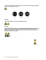
Collegare tutti i fili elettrici a una presa di alimentazione correttamente cablata e dotata di messa a
terra.
•
Collegare alle prese elettriche appropriate tutte le apparecchiature che verranno utilizzate per
questo prodotto.
•
Se possibile, utilizzare solo una mano per collegare o scollegare i cavi di segnale.
•
Non accendere assolutamente apparecchiature in presenza di incendi, perdite d'acqua o danno
strutturale.
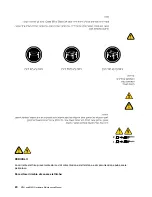
•
Scollegare i cavi di alimentazione, i sistemi di telecomunicazione, le reti e il modem prima di aprire i
coperchi del dispositivo, salvo istruzioni contrarie relative alle procedure di installazione e
configurazione.
•
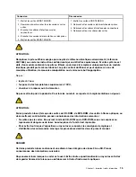
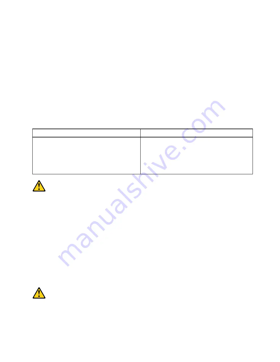
Collegare e scollegare i cavi come descritto nella seguente tabella quando vengono effettuate
operazioni di installazione, spostamento o apertura dei coperchi di questo prodotto o delle unità
collegate.
Per collegarsi
Per scollegarsi
1. SPEGNERE le apparecchiature.
2. Innanzitutto, collegare tutti i cavi alle unità.
3. Collegare i cavi di segnale ai connettori.
4. Collegare i cavi di alimentazione alla presa.
5. Accendere l'unità.
1. SPEGNERE le apparecchiature.
2. Innanzitutto, rimuovere i cavi di alimentazione dalla
presa.
3. Rimuovere i cavi di segnale dai connettori.
4. Rimuovere tutti i cavi dalle unità.
ATTENZIONE:
Quando si sostituisce la batteria al litio, utilizzare solo il Numero parte 45C1566 o un tipo di batteria
equivalente consigliato dal produttore. Se sul sistema è presente un modulo che contiene una batteria
al litio, sostituirlo solo con un tipo di modulo dello stesso tipo della stessa casa di produzione. La
batteria contiene litio e può esplodere se usata, maneggiata o smaltita in modo non corretto.
Non:
•
Gettare o immergere la batteria nell'acqua
•
Riscaldarla ad una temperatura superiore ai 100 gradi C (212 gradi F)
•
Smontarla, ricaricarla o tentare di ripararla
Le batterie usate vanno smaltite in accordo alla normativa in vigore (DPR 915/82 e successive
disposizioni e disposizioni locali).
ATTENZIONE:
Quando vengono installati prodotti laser (quali CD-ROM, unità DVD-ROM, unità a fibre ottiche o
trasmittenti), tener presente quanto segue:
.
21
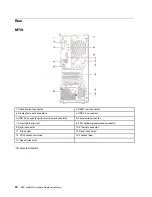
Summary of Contents for ThinkCentre M70t
Page 1: ...M70t and M80t Hardware Maintenance Manual ...
Page 6: ...iv M70t and M80t Hardware Maintenance Manual ...
Page 13: ...Chapter 1 Important safety information 7 ...
Page 14: ... 18 kg 37 lb 32 kg 70 5 lb 55 kg 121 2 lb 1 2 8 M70t and M80t Hardware Maintenance Manual ...
Page 17: ...Chapter 1 Important safety information 11 ...
Page 18: ...1 2 12 M70t and M80t Hardware Maintenance Manual ...
Page 19: ...Chapter 1 Important safety information 13 ...
Page 25: ...Chapter 1 Important safety information 19 ...
Page 29: ...Chapter 1 Important safety information 23 ...
Page 38: ...32 M70t and M80t Hardware Maintenance Manual ...
Page 46: ...40 M70t and M80t Hardware Maintenance Manual ...
Page 109: ......
Page 110: ......


