background image

Replacing hardware

Handling static-sensitive devices

Do not open the static-protective package containing the new component until the defective

component has been removed and you are ready to install the new component. Static electricity,

although harmless to you, can seriously damage computer components.

When you handle parts and other computer components, take these precautions to avoid static

damage:

Limit your movement. Movement can cause static electricity to build up around you.
Always handle parts and other computer components carefully. Handle PCI/PCI-Express cards,

memory modules, system boards, and microprocessors by the edges. Never touch any exposed

circuitry.
Prevent others from touching the parts and other computer components.
Touch the static-protective package containing the part to a metal expansion-slot cover or other

unpainted metal surface on the computer for at least two seconds. This reduces static electricity from

the package and your body before you install or replace a new part.
When possible, remove the new part from the static-protective package, and install it directly in the

computer without setting the part down. When this is not possible, place the static-protective package

that the part came in on a smooth, level surface and place the part on the package.
Do not place the part on the computer cover or other metal surface.

© Copyright Lenovo 2016.

11

Summary of Contents for ThinkCentre M715q

Page 1: ...User Guide and Hardware Maintenance Manual M715q Machine Type MT 10M2 10M3 10M4 10M5 Energy Star MT 10M2 10M3 10M4 10M5 1 ...

Page 2: ...ower adapter 18 Vertical stand 19 VESA mount bracket 21 External optical drive 22 I O box 24 Power adapter bracket 25 Internal speaker 27 Mouse 29 Keyboard 31 System fan 32 2 5 inch storage drive 33 M 2 Storage drive 35 Memory module 37 Coin cell battery 39 Wi Fi card 41 Completing the parts replacement 45 Replacing field replaceable units FRUs Before replacing FRUs 47 Replacing FRUs Internal spea...

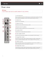
Page 3: ... You can use the microphone to record sounds or use speech recognition software 5 Headset connector Used to connect a headset or headphones to your computer 6 Always On USB 3 0 connector Used to connect a device that requires a USB 2 0 or USB 3 0 connection such as a keyboard a mouse a scanner a printer or a personal digital assistant PDA With the power adapter connected you can charge the automat...

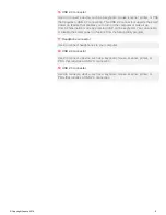
Page 4: ...ter model 11 Security lock slot Used to secure a Kensington style cable lock 12 Power adapter connector Used to connect the power adapter to your computer for power supply 13 DisplayPort connector Used to send or receive audio and video signals An audio or video device such as a high performance monitor can be attached to this connector 14 USB 3 0 connector Used to connect a device such as a keybo...

Page 5: ...e by pressing Alt P on the keyboard You can enable or disable the smart power on feature from the Setup Utility program 17 Headphone connector Used to connect headphones to your computer 18 USB 2 0 connector Used to connect a device such as a keyboard mouse scanner printer or PDA that requires a USB 2 0 connection 19 USB 2 0 connector Used to connect a device such as a keyboard mouse scanner print...

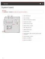
Page 6: ... battery 3 SATA 3 0 storage drive connector 4 System fan connector 5 Optional serial connector 6 Optional display connector 7 M 2 storage drive slot 8 Microprocessor socket 9 Thermal sensor Cover presence switch connector Intrusion switch 10 connector 11 Internal speaker connector 12 Memory slot DIMM 1 13 Memory slot DIMM 2 6 ...

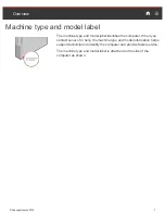
Page 7: ...ntifies the computer When you contact Lenovo for help the machine type and model information helps support technicians to identify the computer and provide faster service The machine type and model label is attached on the side of the computer as shown Copyright Lenovo 2016 7 ...

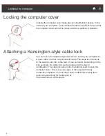
Page 8: ...sington style cable lock to secure your computer to a desk table or other nonpermanent fixture The cable lock connects to the security lock slot at the rear of your computer Depending on the type selected the cable lock can be operated with a key or combination The cable lock also locks the buttons used to open the computer cover This is the same type of lock used with many notebook computers You ...

Page 9: ...ctor Input Output I O Audio connectors headphone connector headset connector and features microphone connector Display connectors DisplayPort connectors and VGA connector optional Ethernet connector Serial connector optional USB connectors Expansion External optical drive box optional Memory slots Storage drive bay Network features Ethernet LAN Wireless LAN optional Bluetooth optional Physical dim...

Page 10: ...ts explained in this manual are optional Use computer components provided only by Lenovo When installing or replacing an option use the appropriate instructions explained in this manual along with the instructions that come with the option In most areas of the world Lenovo requires the return of defective CRUs Customer Replaceable Units Information about this will come with the CRU or will come a ...

Page 11: ...ystem boards and microprocessors by the edges Never touch any exposed circuitry Prevent others from touching the parts and other computer components Touch the static protective package containing the part to a metal expansion slot cover or other unpainted metal surface on the computer for at least two seconds This reduces static electricity from the package and your body before you install or repl...

Page 12: ...nal service CRUs requires some technical skills and simple tools such as a screwdriver These CRUs are isolated parts within the computer They are usually concealed by an access panel that is secured by more than two screws You must remove the screws and panel to access the specific CRU Optional service CRUs can be removed and installed by users or during the warranty period by a Lenovo service tec...

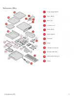
Page 13: ... 2 2 2 Power adapter 3 3 Power cord 4 4 Computer cover 5 5 Vertical stand 10 Internal speaker 13 Keyboard 14 14 Mouse 23 VESA mount bracket 24 External optical drive 26 I O box 25 External optical drive box 23 Copyright Lenovo 2016 13 2 3 4 5 ...

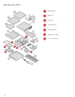
Page 14: ...Optional service CRUs 7 Memory module 12 System fan 16 Wi Fi card 17 Coin cell battery 18 M 2 storage drive 21 Storage drive bracket 22 2 5 inch storage drive 14 ...

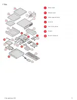
Page 15: ...FRUs Copyright Lenovo 2016 15 6 System board 8 Microprocessor 9 Internal speaker holder 11 Heat sink 15 Front Wi Fi antenna 19 Chassis 22 Rear Wi Fi antenna ...

Page 16: ...acing the power adapter 18 Replacing the vertical stand 19 Replacing the VESA mount bracket 21 Replacing the external optical drive 22 Replacing the I O box 24 Replacing the power adapter bracket 25 Replacing the internal speaker 27 Replacing the mouse 29 Replacing the keyboard 31 Optional service CRU procedures Replacing the system fan 32 Replacing the 2 5 inch storage drive 33 Replacing the M 2 ...

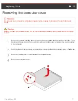
Page 17: ...tes until the computer is cool 1 Remove any media from the drives and turn off all connected devices and the computer Then disconnect all power cords from electrical outlets and disconnect all cables that are connected to the computer 2 Hold the sides of your computer and gently lay it down so that the computer cover is facing up 3 Unlock any locking device that secures the computer cover 4 Remove...

Page 18: ...cted devices and the computer Then disconnect all power cords from electrical outlets and disconnect all cables that are connected to the computer 2 If the power adapter bracket is available remove the power adapter bracket See Replacing the power adapter bracket 3 Replace the power adapter 1 2 4 If the power adapter bracket is available install the power adapter bracket See Replacing the power ad...

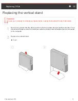
Page 19: ...ading the Important Product Information Guide 1 Remove any media from the drives and turn off all connected devices and the computer Then disconnect all power cords from electrical outlets and disconnect all cables that are connected to the computer 2 Replace the vertical stand Type1 1 2 Copyright Lenovo 2016 19 ...

Page 20: ...Type2 1 2 20 ...

Page 21: ...s and the computer Then disconnect all power cords from electrical outlets and disconnect all cables that are connected to the computer 2 If the power adapter bracket is available remove the power adapter bracket See Replacing the power adapter bracket 3 Replace the VESA mount bracket 1 2 4 If the power adapter bracket is available install the power adapter bracket See Replacing the power adapter ...

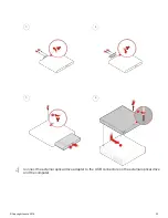
Page 22: ... 1 Remove any media from the drives and turn off all connected devices and the computer Then disconnect all power cords from electrical outlets and disconnect all cables that are connected to the computer 2 Disconnect the external optical drive adapter from the USB connectors on the external optical drive and the computer 3 Replace the external optical drive 1 2 22 ...

Page 23: ...3 4 5 6 4 Connect the external optical drive adapter to the USB connectors on the external optical drive and the computer Copyright Lenovo 2016 23 ...

Page 24: ... any media from the drives and turn off all connected devices and the computer Then disconnect all power cords from electrical outlets and disconnect all cables that are connected to the computer 2 Disconnect the I O box cable from the USB connectors on the computer 3 Replace the I O box 1 2 4 Connect the I O box cable to the USB connectors on the computer 24 ...

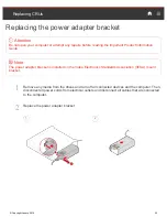
Page 25: ...he power adapter bracket is installed on the Video Electronics Standards Association VESA mount bracket 1 Remove any media from the drives and turn off all connected devices and the computer Then disconnect all power cords from electrical outlets and disconnect all cables that are connected to the computer 2 Replace the power adapter bracket 1 2 Copyright Lenovo 2016 25 ...

Page 26: ...3 4 26 ...

Page 27: ...f all connected devices and the computer Then disconnect all power cords from electrical outlets and disconnect all cables that are connected to the computer 2 Remove the computer cover For details see Removing the computer cover 3 Record the routing and connection of the internal speaker cable and then disconnect the cable from the system board 4 Replace the internal speaker 1 2 Copyright Lenovo ...

Page 28: ... 5 Connect the cable of the new internal speaker to the internal speaker connector on the system board 6 Reinstall the removed parts and computer cover For details see Completing the parts replacement 28 ...

Page 29: ... models 1 Remove any media from the drives and turn off all connected devices and the computer Then disconnect all power cords from electrical outlets and disconnect all cables that are connected to the computer 2 Disconnect the USB dongle from your computer Then take away your failing wireless mouse 3 Remove the new wireless mouse from the package 4 Replace the wireless mouse 1 Copyright Lenovo 2...

Page 30: ...mber LED indicates a low battery power level Push the power switch to the off position when you are not using the mouse to extend the battery life After disconnecting the USB dongle from your computer store it in the wireless mouse compartment or in the wireless keyboard compartment 30 ...

Page 31: ...er cords from electrical outlets and disconnect all cables that are connected to the computer 2 Remove your failing wireless keyboard 3 Take out the new wireless keyboard from the package 4 Open the battery compartment cover and install two AAA batteries according to the polarity indicators 5 Take away the USB dongle from the keyboard compartment or from the wireless mouse compartment and connect ...

Page 32: ...rical outlets and disconnect all cables that are connected to the computer 2 Remove the computer cover For details see Removing the computer cover 3 Record the routing and connection of the system fan cable and then disconnect the cable from the system board 4 Replace the system fan 1 2 32 5 Connect the cable of the new system fan to the system fan connector on the system board 6 Reinstall the com...

Page 33: ...es and turn off all connected devices and the computer Then disconnect all power cords from electrical outlets and disconnect all cables that are connected to the computer 2 Remove the computer cover For details see Removing the computer cover 3 Remove the storage drive bracket Note Carefully handle the storage drive bracket to avoid breaking the front Wi Fi antenna cable Copyright Lenovo 2016 33 ...

Page 34: ...4 Replace the 2 5 inch storage drive 1 2 5 Reinstall the storage drive bracket 6 Reinstall the computer cover and reconnect the cables For details see Completing the parts replacement 34 ...

Page 35: ... and turn off all connected devices and the computer Then disconnect all power cords from electrical outlets and disconnect all cables that are connected to the computer 2 Remove the computer cover For details see Removing the computer cover 3 Remove the storage drive bracket For details see Replacing the 2 5 inch storage drive 4 Replace the M 2 storage drive Type1 1 2 3 4 Copyright Lenovo 2016 ...

Page 36: ...Type2 1 2 3 4 5 Reinstall the removed parts and computer cover and then reconnect the cables For details see Completing the parts replacement 36 ...

Page 37: ...y module into the DIMM 1 slot first and then install the other into the DIMM 2 slot 1 Remove any media from the drives and turn off all connected devices and the computer Then disconnect all power cords from electrical outlets and disconnect all cables that are connected to the computer 2 Remove the computer cover For details see Removing the computer cover 3 Remove the storage drive bracket For d...

Page 38: ...3 4 5 Reinstall the removed parts and computer cover and then reconnect the cables For details see Completing the parts replacement 38 ...

Page 39: ...hout its life however no coin cell battery lasts forever If the coin cell battery fails the date time and configuration information including passwords are lost An error message is displayed when you turn on the computer To replace the coin cell battery 1 Remove any media from the drives and turn off all connected devices and the computer Then disconnect all power cords from electrical outlets and...

Page 40: ... parts and computer cover and then reconnect the cables For details see Completing the parts replacement To dispose of the coin cell battery refer to the Lithium coin cell battery notice topic in the Safety and Warranty Guide 40 ...

Page 41: ...ove any media from the drives and turn off all connected devices and the computer Then disconnect all power cords from electrical outlets and disconnect all cables that are connected to the computer 2 Remove the computer cover For details see Removing the computer cover 3 Remove the storage drive bracket For details see Replacing the 2 5 inch storage drive 4 Remove the Wi Fi card cover Type1 Copyr...

Page 42: ...Type2 5 Replace the Wi Fi card Type1 1 2 3 4 42 ...

Page 43: ...Type2 1 2 3 4 6 Reinstall the Wi Fi card cover Type1 Copyright Lenovo 2016 43 ...

Page 44: ...Type 2 7 Reinstall the removed parts and computer cover and then reconnect the cables For details see Completing the parts replacement 44 ...

Page 45: ... To reinstall the computer cover and reconnect the cables to your computer do the following 1 Ensure that all components have been reassembled correctly and that no tools or loose screws are left inside your computer 2 Ensure that the cables are routed correctly before reinstalling the computer cover Keep cables clear of the hinges and sides of the computer chassis to avoid interference when reins...

Page 46: ...stall the screw to secure the computer cover 5 If a locking device is available use it to lock the computer 6 Reconnect the external cables and power cords to the corresponding connectors on the computer 46 ...

Page 47: ...ducible failure Single failures can occur for a variety of reasons that have nothing to do with a hardware defect such as cosmic radiation electrostatic discharge or software errors Consider replacing an FRU only when a problem recurs If you suspect that an FRU is defective clear the error log and run the test again If the error does not recur do not replace the FRU Only replace a defective FRU To...

Page 48: ...d to the computer 2 Remove the computer cover For details see Removing the computer cover 3 Record the routing and connection of the internal speaker cable and then disconnect the cable from the system board 4 Remove the internal speaker For details see Replacing the internal speaker 5 Replace the internal speaker holder 1 2 6 Connect the cable of the internal speaker to the internal speaker conne...

Page 49: ... drives and turn off all connected devices and the computer Then disconnect all power cords from electrical outlets and disconnect all cables that are connected to the computer 2 Remove the computer cover For details see Removing the computer cover 3 Remove the system fan For details see Replacing the system fan 4 Remove the internal speaker For details see Replacing the internal speaker 5 Remove ...

Page 50: ...1 2 7 Reinstall the removed parts and computer cover and then reconnect the cables For details see Completing the parts replacement 50 ...

Page 51: ...or details see Removing the computer cover 3 Remove the system fan For details see Replacing the system fan 4 Remove the internal speaker For details see Replacing the internal speaker 5 Remove the internal speaker holder For details see Replacing the internal speaker holder 6 Remove the heat sink For details see Replacing the heat sink Then ected 7 Disconnect all cables connected to the system bo...

Page 52: ...1 2 3 4 5 6 52 ...

Page 53: ...hat were disconnected from the system board For details see System board 10 Reinstall the removed parts and computer cover and then reconnect the cables For details see Completing the parts replacement Copyright Lenovo 2016 53 ...

Page 54: ...er Then disconnect all power cords from electrical outlets and disconnect all cables that are connected to the computer 2 Remove the computer cover For details see Removing the computer cover 3 Remove the storage drive bracket For details see Replacing the 2 5 inch storage drive 4 Remove the Wi Fi card cover For details see Replacing the Wi Fi card 5 Disconnect the front antenna cable from the Wi ...

Page 55: ...3 7 Connect the front antenna cable to the Wi Fi card Reinstall the removed parts and computer cover and then reconnect the cables For details see Completing the parts replacement Copyright Lenovo 2016 55 ...

Page 56: ... the drives and turn off all connected devices and the computer Then disconnect all power cords from electrical outlets and disconnect all cables that are connected to the computer 2 Straighten the rear Wi Fi antenna so that it can be more easily twisted 3 Replace the rear Wi Fi antenna 1 2 4 Adjust the angle of the rear antenna to lower the risk of breaking the antenna by accident 56 ...

Page 57: ...al speaker For details see Replacing the internal speaker 5 Remove the internal speaker holder For details see Replacing the internal speaker holder 6 Remove the heat sink For details see Replacing the heat sink 7 Remove the storage drive bracket For details see Replacing the 2 5 inch storage drive 8 Remove the M 2 storage drive For details see Replacing the M 2 storage drive 9 Remove the memory m...

Page 58: ...oute all the cables that you disconnected from the failing system board and then reconnect the cables to the new system board For details see System board 15 Reinstall the removed parts and computer cover and then reconnect the cables For details see Completing the parts replacement 58 ...

Page 59: ... To reinstall the computer cover and reconnect the cables to your computer do the following 1 Ensure that all components have been reassembled correctly and that no tools or loose screws are left inside your computer 2 Ensure that the cables are routed correctly before reinstalling the computer cover Keep cables clear of the hinges and sides of the computer chassis to avoid interference when reins...

Page 60: ...stall the screw to secure the computer cover 5 If a locking device is available use it to lock the computer 6 Reconnect the external cables and power cords to the corresponding connectors on the computer 60 ...

Page 61: ...f the publication Lenovo may make improvements and or changes in the product s and or the program s described in this publication at any time without notice The products described in this document are not intended for use in implantation or other life support applications where malfunction may result in injury or death to persons The information contained in this document does not affect or change...

Page 62: ...he United States other countries or both Lenovo The Lenovo logo ThinkCentre ThinkCentre logo DisplayPort and VESA are trademarks of the Video Electronics Standards Association Other company product or service names may be trademarks or service marks of others 62 ...

Page 63: ......

Page 64: ... Lenovo 2016 LIMITED AND RESTRICTED RIGHTS NOTICE If data or software is delivered pursuant to a General Services Administration GSA contract use reproduction or disclosure is subject to restrictions set forth in Contract No GS 35F 05925 ...

Reviews: