background image

ThinkCentre M720s User Guide and Hardware 
Maintenance Manual

Energy Star Machine Types: 

10ST, 10SU, 10SV, 10TR, 10U6, and 

10U7

Summary of Contents for ThinkCentre M720s

Page 1: ...ThinkCentre M720s User Guide and Hardware Maintenance Manual Energy Star Machine Types 10ST 10SU 10SV 10TR 10U6 and 10U7 ...

Page 2: ...formation Guide and Appendix A Notices on page 71 First Edition June 2018 Copyright Lenovo 2018 LIMITED AND RESTRICTED RIGHTS NOTICE If data or software is delivered pursuant to a General Services Administration GSA contract use reproduction or disclosure is subject to restrictions set forth in Contract No GS 35F 05925 ...

Page 3: ... bezel 25 Replacing the optical drive 25 Replacing the storage drive 27 Replacing a memory module 33 Replacing a PCI Express card 35 Replacing the Wi Fi card 37 Replacing the M 2 solid state drive 39 Replacing the M 2 solid state drive bracket 46 Replacing the power supply assembly 46 Replacing the Wi Fi antennas 48 Replacing the internal speaker 50 Replacing the illuminated red dot cable 52 Repla...

Page 4: ...ii ThinkCentre M720s User Guide and Hardware Maintenance Manual ...

Page 5: ...ew This chapter provides basic information to help you get familiar with your computer Front view Note Your computer model might look slightly different from the illustration Figure 1 Front view Copyright Lenovo 2018 1 ...

Page 6: ... slot optional Used to read data from a supported memory card 5 Power button Used to turn on your computer When you cannot shut down the computer from the operating system press and hold the power button for four or more seconds to turn off the computer 6 Power indicator This indicator is on when the computer is on 7 Microphone connector Used to connect a microphone to your computer You can use th...

Page 7: ... a USB 3 1 Gen 1 or USB 2 0 connector 12 Illuminated red dot This indicator is on when the computer is on 13 Internal speaker Used to listen to the sounds from your computer without using a headset or headphones Rear view Note Your computer model might look slightly different from the illustration Figure 2 Rear view Chapter 1 Overview 3 ...

Page 8: ...send video signals from the computer to another video device such as a monitor 3 DisplayPort 1 2 out connectors Used to send audio and video signals from the computer to another audio or video device such as a high performance monitor 4 USB 2 0 connector Used to connect a device that requires a USB 2 0 connection Note The USB 2 0 connector supports the smart power on feature If you connect a Lenov...

Page 9: ...uter you can connect PCI Express cards into this area Depending on the computer model the connectors in this area vary 12 Smart cable clip slots optional Used to secure a smart cable clip 13 Power cord connector Used to connect the power cord to your computer for power supply System board Note See Front view and Rear view for additional component descriptions Chapter 1 Overview 5 ...

Page 10: ...nectors 3 11 M 2 solid state drive slot 12 M 2 Wi Fi card slot 13 Thermal sensor connector 14 Illuminated red dot connector 15 Front USB 2 0 connector 16 Parallel connector 17 Serial COM2 connector 18 PCI Express x1 card slots 2 19 PCI Express x16 graphics card slot 20 System fan connector 21 E lock connector 22 Microprocessor socket 23 Cover presence switch connector Intrusion switch connector 24...

Page 11: ...e and model label identifies the computer When you contact Lenovo for help the machine type and model information helps support technicians to identify the computer and provide faster service The machine type and model label is attached on the computer as shown Figure 4 Machine type and model label Chapter 1 Overview 7 ...

Page 12: ...8 ThinkCentre M720s User Guide and Hardware Maintenance Manual ...

Page 13: ...d supports the following Audio line out connector Headset connector Internal speaker Microphone connector optional The optional discrete audio card provides an enhanced audio experience and extended capabilities Input Output I O features Audio connectors audio line out headset and microphone Card reader slot optional VGA out connector Ethernet connector PS 2 keyboard connector optional PS 2 mouse ...

Page 14: ...LAN Wireless LAN optional Bluetooth optional Physical dimensions Width 92 5 mm 3 6 inches Height 343 5 mm 13 5 inches Depth 290 5 mm 11 4 inches Weight without the package Maximum configuration as shipped 6 kg 13 2 lb 10 ThinkCentre M720s User Guide and Hardware Maintenance Manual ...

Page 15: ...r computer may have a security lock solution installed to protect the computer from unauthorized tampering of the internal components Using the E Lock you can mechanically lock or unlock the computer cover To enable or disable the E Lock do the following 1 Turn on or restart the computer 2 Before Windows starts up repeatedly press and release the F1 or Fn F1 key until the Setup Utility program ope...

Page 16: ... order such a cable lock directly from Lenovo by searching for Kensington at http www lenovo com support Figure 7 Attaching a Kensington style cable lock Attaching a smart cable clip A smart cable clip can be used to secure devices such as the keyboard and the mouse by locking the device cables to the computer The smart cable clip connects to the cable lock slots on the rear of the computer To ins...

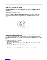
Page 17: ...Figure 8 Attaching a smart cable clip Chapter 3 Computer locks 13 ...

Page 18: ...14 ThinkCentre M720s User Guide and Hardware Maintenance Manual ...

Page 19: ...try Prevent others from touching the options and other computer components Touch the static protective package containing the part to a metal expansion slot cover or other unpainted metal surface on the computer for at least two seconds This reduces static electricity from the package and your body before you install or replace a new part When possible remove the new part from the static protectiv...

Page 20: ... an FRU only with another FRU of the correct model When you replace an FRU ensure that the model of the machine and the FRU part number are correct An FRU should not be replaced because of a single unreproducible failure Single failures can occur for a variety of reasons that have nothing to do with a hardware defect such as cosmic radiation electrostatic discharge or software errors Consider repl...

Page 21: ...10 Wi Fi card 3 Heat sink and fan assembly 2 PCI Express card 11 Wi Fi card shield 4 Microprocessor 6 Memory module 36 Power supply assembly 5 System board 8 M 2 solid state drive heat sink 37 E lock 7 Coin cell battery 9 M 2 solid state drive 15 Power button Chapter 4 Replacing hardware 17 ...

Page 22: ...Storage converter 34 Primary storage drive bracket Replacing the keyboard or wireless keyboard Note The wireless keyboard is available only on some models Replacing the keyboard 1 Turn off the computer and disconnect all power cords from electrical outlets 2 Disconnect the old keyboard cable from the computer 3 Connect a new keyboard to the appropriate connector on the computer Figure 10 Replacing...

Page 23: ...dels Replacing the mouse 1 Turn off the computer and disconnect all power cords from electrical outlets 2 Disconnect the old mouse cable from the computer 3 Connect a new mouse to the appropriate connector on the computer Figure 12 Replacing the mouse Replacing the wireless mouse 1 Disconnect the USB dongle from your computer Then remove your old wireless mouse 2 Take out the new wireless mouse fr...

Page 24: ...the battery compartment Figure 14 Taking out the USB dongle Figure 15 Connecting the USB dongle to a USB connector Figure 16 Installing the mouse batteries 20 ThinkCentre M720s User Guide and Hardware Maintenance Manual ...

Page 25: ... your computer store it in the wireless mouse compartment or in the wireless keyboard compartment Replacing the power cord Attention Do not open your computer or attempt any repairs before reading the Important Product Information Guide 1 Remove any media from the drives and turn off all connected devices and the computer 2 Disconnect all power cords from electrical outlets and disconnect all cabl...

Page 26: ...airs before reading the Important Product Information Guide 1 Remove any media from the drives and turn off all connected devices and the computer 2 Disconnect all power cords from electrical outlets and disconnect all cables that are connected to the computer 3 Replace the dust shield Figure 21 Removing the dust shield 22 ThinkCentre M720s User Guide and Hardware Maintenance Manual ...

Page 27: ...pt any repairs before reading the Important Product Information Guide 1 Remove any media from the drives and turn off all connected devices and the computer 2 Disconnect all power cords from electrical outlets and disconnect all cables that are connected to the computer 3 Replace the vertical stand Figure 23 Removing the vertical stand Chapter 4 Replacing hardware 23 ...

Page 28: ...er cover turn off the computer and wait several minutes until the computer is cooled down 1 Remove any media from the drives and turn off all connected devices and the computer 2 Disconnect all power cords from electrical outlets and disconnect all cables that are connected to the computer 3 Unlock any locking device that secures the computer cover 4 Remove the dust shield See Replacing the dust s...

Page 29: ...4 2 Replace the front bezel Figure 26 Removing the front bezel Figure 27 Installing the front bezel 3 Complete the replacement See Completing the parts replacement on page 68 Replacing the optical drive Attention Do not open your computer or attempt any repairs before reading the Important Product Information Guide 1 Remove the computer cover See Removing the computer cover on page 24 2 Remove the...

Page 30: ...m the optical drive 4 Replace the optical drive Figure 28 Removing the optical drive assembly Figure 29 Removing the optical drive bracket Figure 30 Installing the optical drive bracket 26 ThinkCentre M720s User Guide and Hardware Maintenance Manual ...

Page 31: ...ding the Important Product Information Guide Replacing the 3 5 inch primary storage drive 1 Remove the computer cover See Removing the computer cover on page 24 2 Remove the front bezel See Replacing the front bezel on page 25 3 Disconnect the storage drive cables from the system board 4 Replace the 3 5 inch primary storage drive Note Ensure that you disconnect or reconnect the storage drive cable...

Page 32: ...e 3 5 inch primary storage drive Figure 34 Removing the 3 5 inch primary storage drive bracket Figure 35 Installing the 3 5 inch primary storage drive bracket 28 ThinkCentre M720s User Guide and Hardware Maintenance Manual ...

Page 33: ...d 6 Complete the replacement See Completing the parts replacement on page 68 Replacing the 2 5 inch primary storage drive 1 Remove the storage converter with the 2 5 inch primary storage drive See Replacing the 3 5 inch primary storage drive 2 Replace the 2 5 inch primary storage drive in the storage converter Chapter 4 Replacing hardware 29 ...

Page 34: ...arts replacement on page 68 Replacing the 2 5 inch secondary storage drive 1 Remove the computer cover See Removing the computer cover on page 24 2 Remove the front bezel See Replacing the front bezel on page 25 3 Replace the 2 5 inch secondary storage drive Note Ensure that you disconnect or reconnect the storage drive cables during the replacement 30 ThinkCentre M720s User Guide and Hardware Mai...

Page 35: ...Figure 40 Opening the drive bay Figure 41 Removing the 2 5 inch secondary storage drive Figure 42 Removing the 2 5 inch secondary storage drive bracket Chapter 4 Replacing hardware 31 ...

Page 36: ...inch secondary storage drive bezel Figure 44 Installing the 2 5 inch secondary storage drive bezel Figure 45 Installing the 2 5 inch secondary storage drive bracket 32 ThinkCentre M720s User Guide and Hardware Maintenance Manual ...

Page 37: ... Replacing a memory module Attention Do not open your computer or attempt any repairs before reading the Important Product Information Guide Notes Before the installation ensure that the memory slot latches are open During the installation ensure that you follow the installation order for memory modules shown in the following figure Chapter 4 Replacing hardware 33 ...

Page 38: ... front bezel See Replacing the front bezel on page 25 3 Replace a memory module Note During the installation ensure that you align the memory module to the slot and press down on both ends until the latches are fully engaged with a click Figure 49 Opening the drive bay 34 ThinkCentre M720s User Guide and Hardware Maintenance Manual ...

Page 39: ...gure 52 Closing the drive bay 4 Complete the replacement See Completing the parts replacement on page 68 Replacing a PCI Express card Attention Do not open your computer or attempt any repairs before reading the Important Product Information Guide Chapter 4 Replacing hardware 35 ...

Page 40: ...you remove the PCI Express card press the latch to disengage it from the slot Then gently remove the card from the slot Figure 53 Opening the drive bay Figure 54 Removing the PCI Express card Note When you install the PCI Express card press down on the rear end of the card until the latch is engaged with a click 36 ThinkCentre M720s User Guide and Hardware Maintenance Manual ...

Page 41: ... page 68 Replacing the Wi Fi card Attention Do not open your computer or attempt any repairs before reading the Important Product Information Guide 1 Remove the computer cover See Removing the computer cover on page 24 2 Remove the front bezel See Replacing the front bezel on page 25 3 Replace the Wi Fi card Chapter 4 Replacing hardware 37 ...

Page 42: ... drive bay Figure 58 Removing the Wi Fi card shield type 1 and type 2 Figure 59 Disconnecting the Wi Fi antennas and removing the Wi Fi card type 1 and type 2 38 ThinkCentre M720s User Guide and Hardware Maintenance Manual ...

Page 43: ...ent on page 68 Replacing the M 2 solid state drive Attention Do not open your computer or attempt any repairs before reading the Important Product Information Guide 1 Remove the computer cover See Removing the computer cover on page 24 2 Remove the front bezel See Replacing the front bezel on page 25 3 Depending on your computer model refer to one of the following to replace the M 2 solid state dr...

Page 44: ...Figure 63 Opening the drive bay Figure 64 Removing the M 2 solid state drive heat sink 40 ThinkCentre M720s User Guide and Hardware Maintenance Manual ...

Page 45: ...Figure 65 Unlocking the M 2 solid state drive clip Figure 66 Removing the M 2 solid state drive Figure 67 Installing the M 2 solid state drive Chapter 4 Replacing hardware 41 ...

Page 46: ...ure 68 Locking the M 2 solid state drive clip Figure 69 Installing the M 2 solid state drive heat sink Figure 70 Closing the drive bay Type 2 42 ThinkCentre M720s User Guide and Hardware Maintenance Manual ...

Page 47: ...Figure 71 Opening the drive bay Figure 72 Removing the M 2 solid state drive heat sink Chapter 4 Replacing hardware 43 ...

Page 48: ...gure 73 Unlocking the M 2 solid state drive clip Figure 74 Removing the M 2 solid state drive Figure 75 Installing the M 2 solid state drive 44 ThinkCentre M720s User Guide and Hardware Maintenance Manual ...

Page 49: ... M 2 solid state drive clip Figure 77 Installing the M 2 solid state drive heat sink Figure 78 Closing the drive bay 4 Complete the replacement See Completing the parts replacement on page 68 Chapter 4 Replacing hardware 45 ...

Page 50: ...2 solid state drive See Replacing the M 2 solid state drive on page 39 4 Replace the M 2 solid state drive bracket Figure 79 Removing the M 2 solid state drive bracket Figure 80 Installing the M 2 solid state drive bracket 5 Complete the replacement See Completing the parts replacement on page 68 Replacing the power supply assembly Attention Do not open your computer or attempt any repairs before ...

Page 51: ...zardous voltage current and energy levels are present inside any component that has this label attached There are no serviceable parts inside these components If you suspect a problem with one of these parts contact a service technician 1 Remove the computer cover See Removing the computer cover on page 24 2 Remove the front bezel See Replacing the front bezel on page 25 3 Replace the power supply...

Page 52: ...Closing the drive bay 4 Complete the replacement See Completing the parts replacement on page 68 Replacing the Wi Fi antennas Attention Do not open your computer or attempt any repairs before reading the Important Product Information Guide 48 ThinkCentre M720s User Guide and Hardware Maintenance Manual ...

Page 53: ...eplace the front Wi Fi antenna Figure 85 Removing the front Wi Fi antenna Figure 86 Installing the front Wi Fi antenna 5 Complete the replacement See Completing the parts replacement on page 68 Replacing the rear Wi Fi antenna 1 Remove any media from the drives and turn off all connected devices and the computer 2 Disconnect all power cords from electrical outlets and disconnect all cables that ar...

Page 54: ...omputer or attempt any repairs before reading the Important Product Information Guide 1 Remove the computer cover See Removing the computer cover on page 24 2 Remove the front bezel See Replacing the front bezel on page 25 3 Disconnect the internal speaker cable from the system board 4 Replace the internal speaker 50 ThinkCentre M720s User Guide and Hardware Maintenance Manual ...

Page 55: ...Figure 89 Opening the drive bay Figure 90 Removing the internal speaker Figure 91 Installing the internal speaker Chapter 4 Replacing hardware 51 ...

Page 56: ...n your computer or attempt any repairs before reading the Important Product Information Guide 1 Remove the computer cover See Removing the computer cover on page 24 2 Remove the front bezel See Replacing the front bezel on page 25 3 Disconnect the illuminated red dot cable from the system board 4 Replace the illuminated red dot Figure 93 Opening the drive bay 52 ThinkCentre M720s User Guide and Ha...

Page 57: ...Figure 94 Removing the sleeve Figure 95 Removing the illuminated red dot cable Figure 96 Installing the illuminated red dot cable Chapter 4 Replacing hardware 53 ...

Page 58: ...thermal sensor Attention Do not open your computer or attempt any repairs before reading the Important Product Information Guide 1 Remove the computer cover See Removing the computer cover on page 24 2 Remove the front bezel See Replacing the front bezel on page 25 3 Disconnect the thermal sensor cable from the system board 4 Replace the thermal sensor 54 ThinkCentre M720s User Guide and Hardware ...

Page 59: ...Figure 99 Opening the drive bay Figure 100 Removing the thermal sensor Figure 101 Installing the thermal sensor Chapter 4 Replacing hardware 55 ...

Page 60: ...or attempt any repairs before reading the Important Product Information Guide 1 Remove the computer cover See Removing the computer cover on page 24 2 Remove the front bezel See Replacing the front bezel on page 25 3 Disconnect the power button cable and the card reader cable from the system board 4 Replace the front I O bracket Figure 103 Removing the front I O bracket 56 ThinkCentre M720s User G...

Page 61: ... Attention Do not open your computer or attempt any repairs before reading the Important Product Information Guide 1 Remove the computer cover See Removing the computer cover on page 24 2 Remove the front bezel See Replacing the front bezel on page 25 3 Remove the front I O bracket See Replacing the front I O bracket on page 56 4 Replace the power button Figure 105 Removing the power button Chapte...

Page 62: ...puter or attempt any repairs before reading the Important Product Information Guide 1 Remove the computer cover See Removing the computer cover on page 24 2 Remove the front bezel See Replacing the front bezel on page 25 3 Remove the front I O bracket See Replacing the front I O bracket on page 56 4 Replace the card reader board Figure 107 Removing the card reader 58 ThinkCentre M720s User Guide a...

Page 63: ...See Completing the parts replacement on page 68 Replacing the heat sink and fan assembly Attention Do not open your computer or attempt any repairs before reading the Important Product Information Guide CAUTION The heat sink and fan assembly might be very hot Turn off the computer and wait three to five minutes to let the computer cool before removing the computer cover Chapter 4 Replacing hardwar...

Page 64: ...l See Replacing the front bezel on page 25 3 Disconnect the microprocessor fan cable from the system board 4 Replace the heat sink and fan assembly Figure 111 Opening the drive bay Figure 112 Removing the heat sink and fan assembly 60 ThinkCentre M720s User Guide and Hardware Maintenance Manual ...

Page 65: ...Product Information Guide CAUTION The heat sink and microprocessor might be very hot Before you open the computer cover turn off the computer and wait several minutes until the computer is cool 1 Remove the computer cover See Removing the computer cover on page 24 2 Remove the front bezel See Replacing the front bezel on page 25 3 Disconnect the E lock cable from the system board if necessary 4 Re...

Page 66: ...onto the microprocessor socket while it is exposed The socket pins must be kept as clean as possible Figure 115 Unlocking the microprocessor socket retainer Figure 116 Pivoting the microprocessor socket upward Figure 117 Removing the microprocessor 62 ThinkCentre M720s User Guide and Hardware Maintenance Manual ...

Page 67: ...re 120 Locking the microprocessor socket retainer 5 Complete the replacement See Completing the parts replacement on page 68 Replacing the coin cell battery Attention Do not open your computer or attempt any repairs before reading the Important Product Information Guide Chapter 4 Replacing hardware 63 ...

Page 68: ...ts forever If the coin cell battery fails the date time and configuration information including passwords are lost An error message is displayed when you turn on the computer To replace the coin cell battery 1 Remove the computer cover See Removing the computer cover on page 24 2 Remove the front bezel See Replacing the front bezel on page 25 3 Replace the coin cell battery Figure 121 Opening the ...

Page 69: ...battery refer to the Lithium coin cell battery notice topic in the Safety and Warranty Guide Replacing the E lock Attention Do not open your computer or attempt any repairs before reading the Important Product Information Guide Note To remove the screws you need a special tool T15 star wrench 1 Remove the computer cover See Removing the computer cover on page 24 2 Disconnect the E lock cable from ...

Page 70: ...Replacing the cover presence switch Attention Do not open your computer or attempt any repairs before reading the Important Product Information Guide 1 Remove the computer cover See Removing the computer cover on page 24 2 Disconnect the cover presence switch cable from the system board 3 Replace the cover presence switch 66 ThinkCentre M720s User Guide and Hardware Maintenance Manual ...

Page 71: ...e Replacing the front I O bracket on page 56 4 Remove all memory modules See Replacing a memory module on page 33 5 Remove the heat sink and fan assembly See Replacing the heat sink and fan assembly on page 59 6 Remove the microprocessor See Replacing the microprocessor on page 61 7 Remove all PCI Express cards See Replacing a PCI Express card on page 35 8 Remove the Wi Fi card See Replacing the W...

Page 72: ...rts replacement on page 68 Completing the parts replacement After completing the installation or replacement for all parts reinstall the computer cover and reconnect the cables To reinstall the computer cover and reconnect the cables to your computer do the following 1 Ensure that all components have been reassembled correctly and that no tools or loose screws are left inside your computer 68 Thin...

Page 73: ...d interference when reinstalling the computer cover 3 Reinstall the computer cover Figure 133 Reinstalling the computer cover 4 Place the computer in an upright position 5 If a locking device is available use it to lock the computer 6 Reconnect the external cables and power cords to the corresponding connectors on the computer Chapter 4 Replacing hardware 69 ...

Page 74: ...70 ThinkCentre M720s User Guide and Hardware Maintenance Manual ...

Page 75: ...he publication Lenovo may make improvements and or changes in the products and or the programs described in this publication at any time without notice The products described in this document are not intended for use in implantation or other life support applications where malfunction may result in injury or death to persons The information contained in this document does not affect or change Leno...

Page 76: ...72 ThinkCentre M720s User Guide and Hardware Maintenance Manual ...

Page 77: ...United States other countries or both Lenovo The Lenovo logo ThinkCentre The ThinkCentre logo DisplayPort is a trademark of the Video Electronics Standards Association Other company product or service names may be trademarks or service marks of others Copyright Lenovo 2018 73 ...

Page 78: ...74 ThinkCentre M720s User Guide and Hardware Maintenance Manual ...

Page 79: ......

Page 80: ......

Reviews: