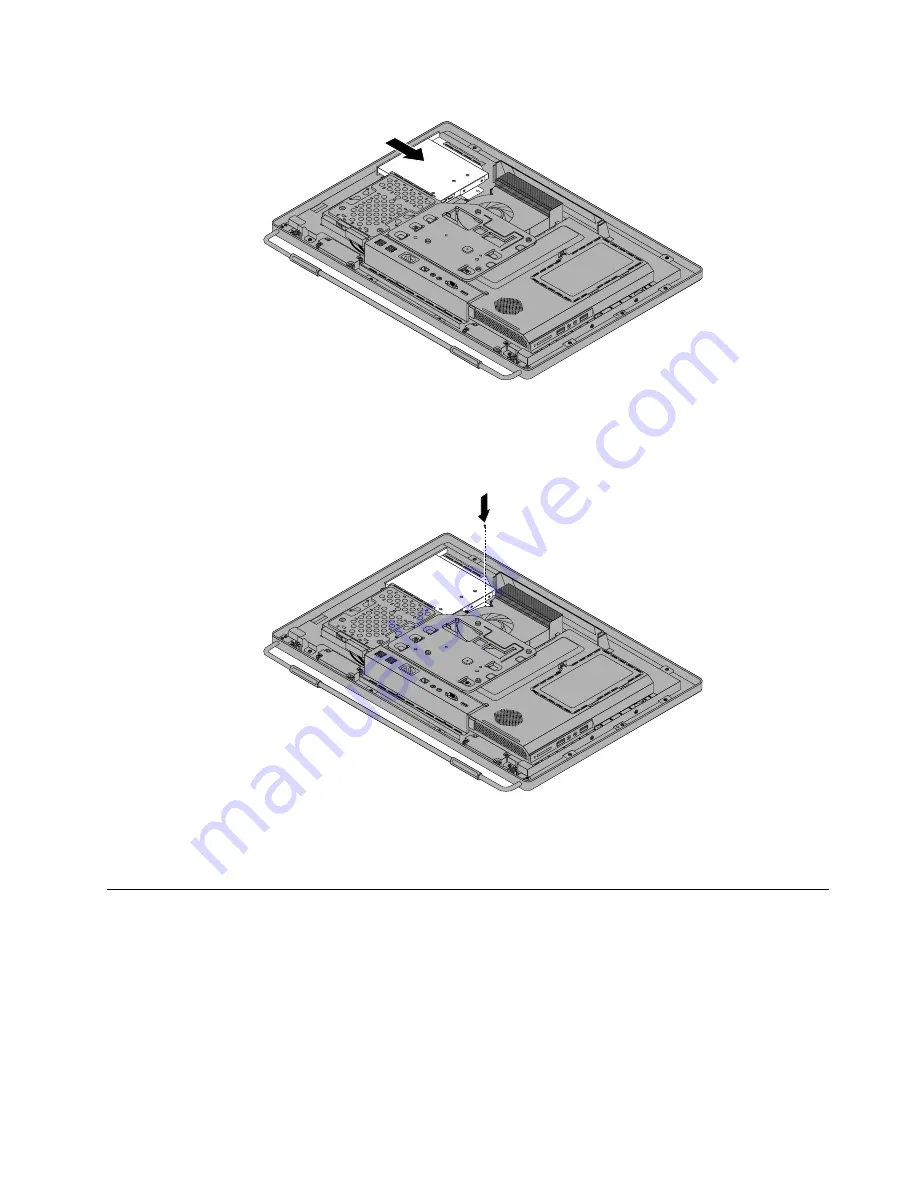
Figure 19. Installing the optical drive
7. Install the screw to secure the optical drive.
Figure 20. Installing the screw to secure the optical drive
8. Go to “Completing the parts replacement” on page 109.
Removing the VESA mount bracket
Attention
Do not open your computer or attempt any repair before reading and understanding the “Important safety
information” in the
Safety , Warranty, and Setup Guide
that came with your computer. To obtain a copy of
the
Safety , Warranty, and Setup Guide
, go to:
http://www.lenovo.com/support
This section provides instructions on how to remove the VESA mount bracket.
Chapter 9
.
Replacing FRUs
83
Summary of Contents for ThinkCentre M72z
Page 2: ......
Page 8: ...2 ThinkCentre Hardware Maintenance Manual ...
Page 15: ...Chapter 2 Safety information 9 ...
Page 19: ...Chapter 2 Safety information 13 ...
Page 20: ...1 2 14 ThinkCentre Hardware Maintenance Manual ...
Page 21: ...Chapter 2 Safety information 15 ...
Page 27: ...Chapter 2 Safety information 21 ...
Page 31: ...Chapter 2 Safety information 25 ...
Page 38: ...32 ThinkCentre Hardware Maintenance Manual ...
Page 68: ...62 ThinkCentre Hardware Maintenance Manual ...
Page 73: ...Figure 3 Locating major FRUs and CRUs Chapter 8 Locations 67 ...
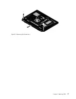
Page 83: ...Figure 12 Removing the frame stand Chapter 9 Replacing FRUs 77 ...
Page 120: ...114 ThinkCentre Hardware Maintenance Manual ...
Page 125: ......
Page 126: ......


