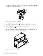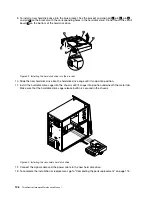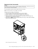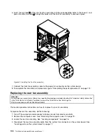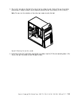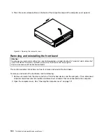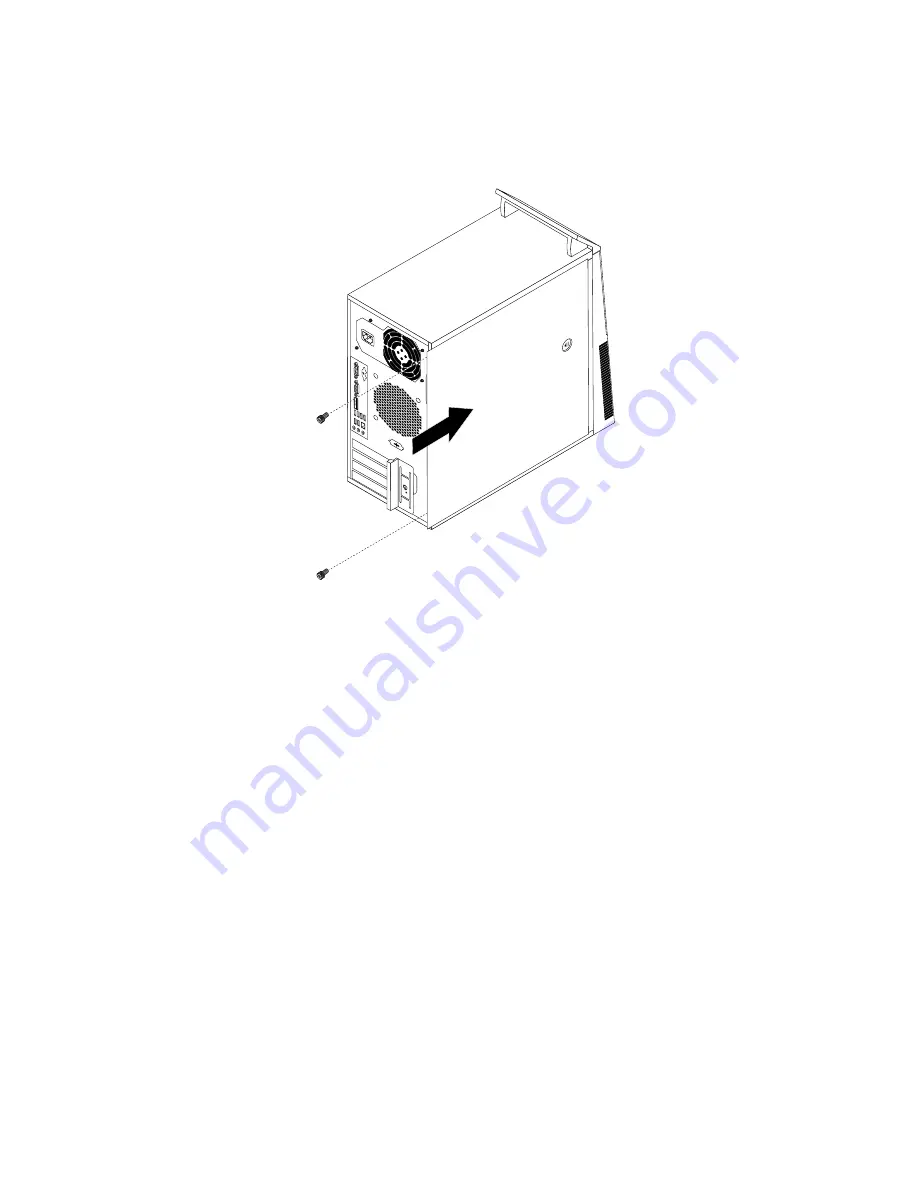
4. Position the computer cover on the chassis so that the rail guides on the bottom of the computer
cover engage the rails. Then, slide the computer cover to the front of the computer until it snaps
into position and is closed.
Figure 48. Reinstalling the computer cover
5. Install the screws to secure the computer cover. See “Removing the computer cover” on page 79.
6. If there is a padlock available, lock the computer cover.
7. If there is an integrated cable lock available, lock the computer.
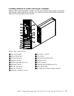
8. Reconnect the external cables and power cords to the computer. See “Locating connectors on the
rear of your computer” on page 75.
9. To update your configuration, refer to Chapter 6 “Using the Setup Utility program” on page 43.
Note:
In most areas of the world, Lenovo requires the return of the defective Field Replaceable Units (FRUs).
Information about this will come with the new FRUs or will come a few days after you receive the new FRUs.
114
ThinkCentre Hardware Maintenance Manual
Summary of Contents for ThinkCentre M81
Page 6: ...iv ThinkCentre Hardware Maintenance Manual ...
Page 15: ...Chapter 2 Safety information 9 ...
Page 16: ... 18 kg 37 lb 32 kg 70 5 lb 55 kg 121 2 lb 10 ThinkCentre Hardware Maintenance Manual ...
Page 20: ...14 ThinkCentre Hardware Maintenance Manual ...
Page 21: ...1 2 Chapter 2 Safety information 15 ...
Page 22: ...1 2 16 ThinkCentre Hardware Maintenance Manual ...
Page 28: ...22 ThinkCentre Hardware Maintenance Manual ...
Page 29: ...1 2 Chapter 2 Safety information 23 ...
Page 33: ...Chapter 2 Safety information 27 ...
Page 34: ...1 2 28 ThinkCentre Hardware Maintenance Manual ...
Page 38: ...32 ThinkCentre Hardware Maintenance Manual ...
Page 78: ...72 ThinkCentre Hardware Maintenance Manual ...
Page 168: ...162 ThinkCentre Hardware Maintenance Manual ...
Page 370: ...364 ThinkCentre Hardware Maintenance Manual ...
Page 374: ...368 ThinkCentre Hardware Maintenance Manual ...
Page 379: ......
Page 380: ...Part Number 0A74545 Printed in USA 1P P N 0A74545 0A74545 ...

