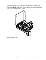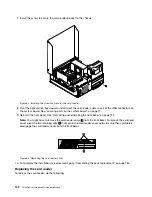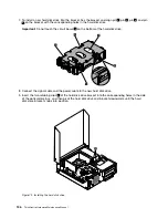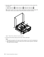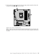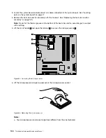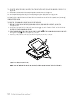
4. Follow this sequence to remove the four screws that secure the heat sink and fan assembly to the
system board:
a. Partially remove screw
1
, then fully remove screw
2
, and then fully remove screw
1
.
b. Partially remove screw
3
, then fully remove screw
4
, and then fully remove screw
3
.
Note:
Carefully remove the four screws from the system board to avoid any possible damage to the
system board. The four screws cannot be removed from the heat sink and fan assembly.
Figure 77. Screws that secure the heat sink and fan assembly
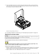
5. Lift the heat sink and fan assembly with the fan duct off the system board.
Notes:
a. You might have to gently twist the heat sink and fan assembly to free it from the microprocessor.
b. When handling the heat sink and fan assembly, do not touch the thermal grease on the bottom
of the heat sink and fan assembly.
140
ThinkCentre Hardware Maintenance Manual
Summary of Contents for ThinkCentre M81
Page 6: ...iv ThinkCentre Hardware Maintenance Manual ...
Page 15: ...Chapter 2 Safety information 9 ...
Page 16: ... 18 kg 37 lb 32 kg 70 5 lb 55 kg 121 2 lb 10 ThinkCentre Hardware Maintenance Manual ...
Page 20: ...14 ThinkCentre Hardware Maintenance Manual ...
Page 21: ...1 2 Chapter 2 Safety information 15 ...
Page 22: ...1 2 16 ThinkCentre Hardware Maintenance Manual ...
Page 28: ...22 ThinkCentre Hardware Maintenance Manual ...
Page 29: ...1 2 Chapter 2 Safety information 23 ...
Page 33: ...Chapter 2 Safety information 27 ...
Page 34: ...1 2 28 ThinkCentre Hardware Maintenance Manual ...
Page 38: ...32 ThinkCentre Hardware Maintenance Manual ...
Page 78: ...72 ThinkCentre Hardware Maintenance Manual ...
Page 168: ...162 ThinkCentre Hardware Maintenance Manual ...
Page 370: ...364 ThinkCentre Hardware Maintenance Manual ...
Page 374: ...368 ThinkCentre Hardware Maintenance Manual ...
Page 379: ......
Page 380: ...Part Number 0A74545 Printed in USA 1P P N 0A74545 0A74545 ...

