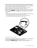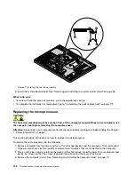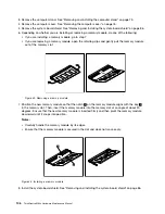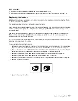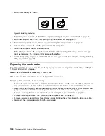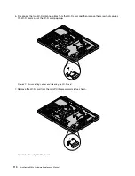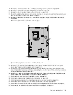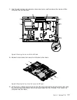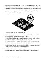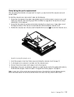
23. Install the system-board shield. See “Removing and installing the system-board shield” on page 86.
24. Install the computer cover. See “Completing the parts replacement” on page 119.
25. Install the computer stand. See “Removing and installing the computer stand” on page 73.
26. Connect the external cables and the power cord to the computer.
The failing system board must be returned with a microprocessor socket cover to protect the pins during
shipping and handling.
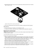
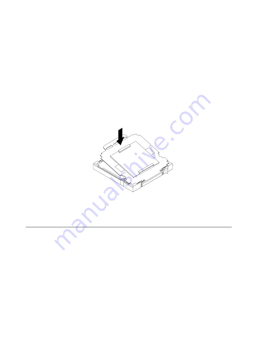
To install the microprocessor socket cover, do the following:
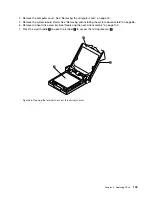
1. After you have removed the microprocessor from the failing system board, close the microprocessor
retainer and then put the lever to the locked position to secure the retainer in place.
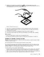
2. Note the orientation of the socket cover, and install one side of the socket cover into the microprocessor
socket. Carefully press the other side of the socket cover downward until the socket cover snaps
into position.
Note:
The microprocessor socket cover might look slightly different from the illustration.
Figure 52. Installing the microprocessor socket cover
3. Carefully check the four corners of the socket cover to ensure that the cover is seated securely.
4. Follow any additional instructions that are included with the replacement part you received.
Replacing the LCD panel
Attention:
Do not open your computer or attempt any repair before reading and understanding the Chapter
1 “Safety information” on page 1.
This section provides instructions on how to replace the liquid crystal display (LCD) panel.
To replace the LCD panel, do the following:
1. Remove all media from the drives and turn off all attached devices and the computer. Then, disconnect
all power cords from electrical outlets and disconnect all cables that are connected to the computer.
2. Place a soft, clean towel or cloth on the desk or other flat surface. Hold the sides of your computer and
gently lay it down so that the screen is against the surface and the cover is facing up.
3. Remove the computer stand. See “Removing and installing the computer stand” on page 73.
4. Remove the computer cover. See “Removing the computer cover” on page 76.
114
ThinkCentre M83z Hardware Maintenance Manual
Summary of Contents for ThinkCentre M83z
Page 1: ...ThinkCentre M83z Hardware Maintenance Manual Machine Types 10C2 and 10C3 ...
Page 6: ......
Page 13: ...Chapter 1 Safety information 7 ...
Page 17: ...Chapter 1 Safety information 11 ...
Page 18: ...1 2 12 ThinkCentre M83z Hardware Maintenance Manual ...
Page 19: ...1 2 Chapter 1 Safety information 13 ...
Page 24: ...1 2 18 ThinkCentre M83z Hardware Maintenance Manual ...
Page 25: ...1 2 Chapter 1 Safety information 19 ...
Page 28: ...22 ThinkCentre M83z Hardware Maintenance Manual ...
Page 32: ...26 ThinkCentre M83z Hardware Maintenance Manual ...
Page 58: ...52 ThinkCentre M83z Hardware Maintenance Manual ...
Page 64: ...58 ThinkCentre M83z Hardware Maintenance Manual ...
Page 70: ...64 ThinkCentre M83z Hardware Maintenance Manual ...
Page 75: ...Figure 3 Locating major FRUs and CRUs Chapter 7 Locations 69 ...
Page 78: ...72 ThinkCentre M83z Hardware Maintenance Manual ...
Page 126: ...120 ThinkCentre M83z Hardware Maintenance Manual ...
Page 136: ...130 ThinkCentre M83z Hardware Maintenance Manual ...
Page 137: ......
Page 138: ......


