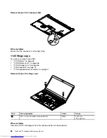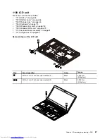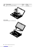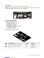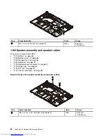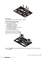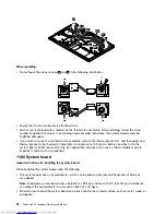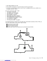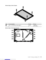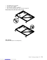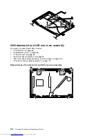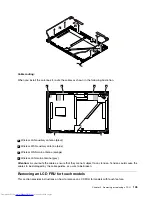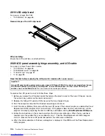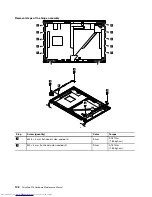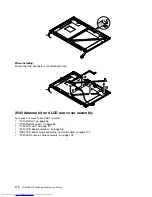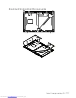
2030 LCD panel, hinge assembly, and LCD cable
For access, remove these FRUs in order:
•
“1010 Battery” on page 65
•
“1020 Bottom cover” on page 66
•
“1130 LCD unit” on page 87
•
“2010 LCD bezel assembly” on page 98
Read this first before replacing the LCD panel for models with a color sensor
Important:
If your LCD panel needs a replacement, order a special LCD panel FRU kit for color sensor model from Lenovo.
The FRU kit contains a LCD panel, a USB key/disc, and an instruction flyer. For the correct FRU kit part
number, check on the Web site at
http://www.lenovo.com/serviceparts-lookup.
To replace the LCD panel, be sure to follow these steps:
1. Before you replace the LCD panel, locate the label on the plastic jacket of the new LCD panel. Locate
the numeric key number on the label and record it.
2. Replace the failing LCD panel with the new one that was shipped to you.
3. Start the computer and enter the Windows operating environment.
4. Insert the disc or USB key that came with the new LCD panel. If the autorun function is enabled, the Panel
Replacement Utility program starts automatically. If the program does not start automatically, run the
program manually by exploring the disc or USB key and double-clicking
PanelReplacementUtility.exe
.
5. Follow the instructions on the screen to perform the initial color calibration. When the key number is
required, type the number that you recorded in step 1. Then the Panel Replacement Utility program
starts to measure the new LCD panel and perform the initial color calibration.
6. When the initial calibration is finished, a dialog box is displayed. Click
OK
to exit the Panel Replacement
Utility program.
Important:
If the computer is protected by a hard disk password or a Windows password, do one of
the following:
• Ask the customer for the password to run the Panel Replacement Utility program.
• Provide the disc/USB key and the numeric key number to the customer and guide the customer to run
the Panel Replacement Utility program.
Failing to run the Panel Replacement Utility program will require another LCD panel replacement.
100
ThinkPad P50 Hardware Maintenance Manual
Summary of Contents for ThinkPad P50
Page 1: ...ThinkPad P50 Hardware Maintenance Manual ...
Page 6: ...iv ThinkPad P50 Hardware Maintenance Manual ...
Page 11: ...DANGER DANGER DANGER DANGER DANGER Chapter 1 Safety information 5 ...
Page 12: ...6 ThinkPad P50 Hardware Maintenance Manual ...
Page 13: ...PERIGO PERIGO PERIGO PERIGO Chapter 1 Safety information 7 ...
Page 14: ...PERIGO PERIGO PERIGO PERIGO DANGER 8 ThinkPad P50 Hardware Maintenance Manual ...
Page 15: ...DANGER DANGER DANGER DANGER DANGER DANGER Chapter 1 Safety information 9 ...
Page 16: ...DANGER VORSICHT VORSICHT VORSICHT VORSICHT 10 ThinkPad P50 Hardware Maintenance Manual ...
Page 17: ...VORSICHT VORSICHT VORSICHT VORSICHT Chapter 1 Safety information 11 ...
Page 18: ...12 ThinkPad P50 Hardware Maintenance Manual ...
Page 19: ...Chapter 1 Safety information 13 ...
Page 20: ...14 ThinkPad P50 Hardware Maintenance Manual ...
Page 21: ...Chapter 1 Safety information 15 ...
Page 22: ...16 ThinkPad P50 Hardware Maintenance Manual ...
Page 23: ...Chapter 1 Safety information 17 ...
Page 24: ...18 ThinkPad P50 Hardware Maintenance Manual ...
Page 28: ...22 ThinkPad P50 Hardware Maintenance Manual ...
Page 46: ...40 ThinkPad P50 Hardware Maintenance Manual ...
Page 64: ...58 ThinkPad P50 Hardware Maintenance Manual ...
Page 122: ...116 ThinkPad P50 Hardware Maintenance Manual ...
Page 123: ......
Page 124: ...Part Number SP40J71944_01 Printed in China 1P P N SP40J71944_01 1PSP40J71944_01 ...

