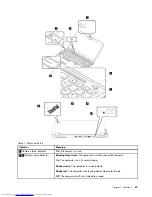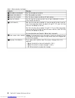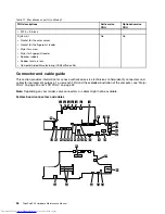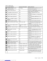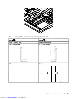
Table 12. System board
No. Connector/feature
Internal cable required
Cable connection
1
Embeded DisplayPort (eDP)
connector (internal)
LCD cable
Connect one end to the LCD panel and the
other end to this connector.
2
HDMI connector (external)
No
Connect a compatible digital audio device or
video monitor to this connector.
3
Thunderbolt connector (external)
No
Connect a compatible device to this
connector.
4
Ethernet connector (external)
No
Connect the computer to a LAN through this
connector.
5
USB 3.0 connector (external)
No
Connect USB-compatible devices to this
connector.
6
Always On USB 3.0 connector
(external)
No
Connect USB-compatible devices to this
connector.
7
Memory module slot (internal)
No
Insert the memory module into this slot.
8
Camera cable connector (internal)
LED camera cable
The LCD comes with the LED camera cable.
Connect the LED camera cable to this
connector.
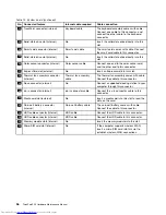
9
Thermal fan assembly connector
(internal)
Thermal fan assembly
cable
The thermal fan assembly comes with cable.
Connect the cable to this connector.
10
Power button connector (internal)
Power button card cable
Connect the power button card cable to this
connector.
11
Mini DisplayPort connector
(external)
No
Connect a compatible projector, external
monitor, or high-definition television to this
connector.
12
USB 3.0 connector (external)
No
Connect USB-compatible devices to this
connector.
13
USB 3.0 connector (external)
No
Connect USB-compatible devices to this
connector.
14
Audio connector (external)
No
Connect headphones or a headset with
3.5-mm (0.14-inch) 4-pole plug to this
connector.
15
Wireless-LAN card/WiGig slot
(internal)
No
Insert the wireless-LAN/WiGig card into this
slot.
16
Wireless-WAN card slot (internal)
No
Insert the wireless-WAN card into this slot.
17
Battery connector (internal)
No
Insert the battery directly to this connector.
18
Speaker connector (internal)
Speaker assembly cable
The speaker assembly comes with cable.
Connect the cable to this connector.
19
Fingerprint reader connector
(internal)
Fingerprint reader cable
Connect one end to the fingerprint reader
card, and the other end to this connector.
20
Trackpad connector (internal)
Trackpad cable
Connect one end to the trackpad and the
other end to this connector.
21
Keyboard connector (internal)
Keyboard cable
The keyboard assembly comes with cable.
Connect one cable to this connector, and
connect the other cable to the TrackPoint
connector.
Chapter 7
.
Locations
55
Summary of Contents for ThinkPad P50
Page 1: ...ThinkPad P50 Hardware Maintenance Manual ...
Page 6: ...iv ThinkPad P50 Hardware Maintenance Manual ...
Page 11: ...DANGER DANGER DANGER DANGER DANGER Chapter 1 Safety information 5 ...
Page 12: ...6 ThinkPad P50 Hardware Maintenance Manual ...
Page 13: ...PERIGO PERIGO PERIGO PERIGO Chapter 1 Safety information 7 ...
Page 14: ...PERIGO PERIGO PERIGO PERIGO DANGER 8 ThinkPad P50 Hardware Maintenance Manual ...
Page 15: ...DANGER DANGER DANGER DANGER DANGER DANGER Chapter 1 Safety information 9 ...
Page 16: ...DANGER VORSICHT VORSICHT VORSICHT VORSICHT 10 ThinkPad P50 Hardware Maintenance Manual ...
Page 17: ...VORSICHT VORSICHT VORSICHT VORSICHT Chapter 1 Safety information 11 ...
Page 18: ...12 ThinkPad P50 Hardware Maintenance Manual ...
Page 19: ...Chapter 1 Safety information 13 ...
Page 20: ...14 ThinkPad P50 Hardware Maintenance Manual ...
Page 21: ...Chapter 1 Safety information 15 ...
Page 22: ...16 ThinkPad P50 Hardware Maintenance Manual ...
Page 23: ...Chapter 1 Safety information 17 ...
Page 24: ...18 ThinkPad P50 Hardware Maintenance Manual ...
Page 28: ...22 ThinkPad P50 Hardware Maintenance Manual ...
Page 46: ...40 ThinkPad P50 Hardware Maintenance Manual ...
Page 64: ...58 ThinkPad P50 Hardware Maintenance Manual ...
Page 122: ...116 ThinkPad P50 Hardware Maintenance Manual ...
Page 123: ......
Page 124: ...Part Number SP40J71944_01 Printed in China 1P P N SP40J71944_01 1PSP40J71944_01 ...

