3
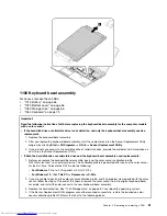
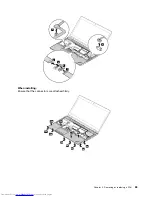
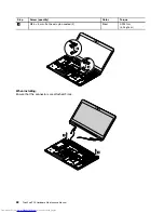
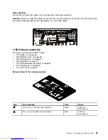
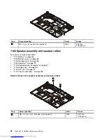
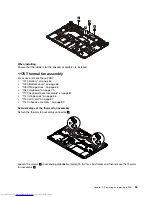
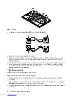
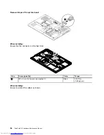
1100 Keyboard bezel assembly
For access, remove these FRUs:
•
“1010 Battery” on page 65
•
“1020 Bottom cover” on page 66
•
“1030 Storage drive” on page 66
•
“1060 Keyboard” on page 73
Important:
Read the following instructions first before replacing the keyboard bezel assembly for the computer models
with a color sensor.
•
If the hard disk drive or solid-state drive is not defective, and only the keyboard bezel assembly needs a
replacement:
1. Replace the keyboard bezel assembly.
2. After you replace the keyboard bezel assembly, start the computer and run the Sensor Replacement Utility
program by clicking
Start
➙
All Programs
➙
X-Rite
➙
Sensor Replacement Utility
.
3. If you do not have access to the hard disk drive or solid-state drive, provide the customer with information on
how to run the Sensor Replacement Utility.
•
If both the hard disk drive or solid-state drive and the keyboard bezel assembly need replacements:
1. Before you replace the keyboard bezel assembly, back up the color sensor calibration profile
ECCM2SensorData.dat
to an external device. This calibration profile is generated after you use the color sensor
for the first time. To locate the DAT file, do the following:
–
For Windows 7
: Go to
C:\ProgramData\X-Rite\ECCM-2
.
–
For Windows 10
: Click
This PC
➙
Documents
➙
X-Rite
.
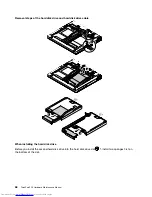
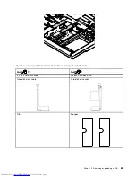
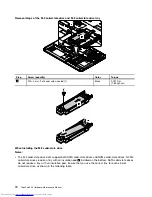
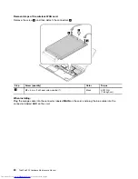
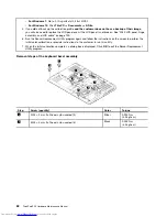
2. If you are unable to back up the color sensor calibration profile, and if no problem was reported with the color
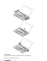
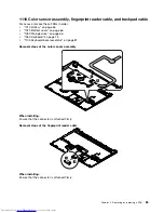
sensor, follow the steps at the end of this topic to remove the color sensor from the original keyboard bezel
assembly, and install the color sensor to the new keyboard bezel assembly.
3. Replace the hard disk drive. See “1030 Storage drive” on page 66. Then reload the operating system.
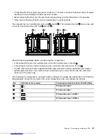
4. If the Sensor Replacement Utility program cannot be launched successfully, restore the backed up color
sensor calibration profile
ECCM2SensorData.dat
to the following places:
Chapter 9
.
Removing or replacing a FRU
81
Summary of Contents for ThinkPad P50
Page 1: ...ThinkPad P50 Hardware Maintenance Manual ...
Page 6: ...iv ThinkPad P50 Hardware Maintenance Manual ...
Page 11: ...DANGER DANGER DANGER DANGER DANGER Chapter 1 Safety information 5 ...
Page 12: ...6 ThinkPad P50 Hardware Maintenance Manual ...
Page 13: ...PERIGO PERIGO PERIGO PERIGO Chapter 1 Safety information 7 ...
Page 14: ...PERIGO PERIGO PERIGO PERIGO DANGER 8 ThinkPad P50 Hardware Maintenance Manual ...
Page 15: ...DANGER DANGER DANGER DANGER DANGER DANGER Chapter 1 Safety information 9 ...
Page 16: ...DANGER VORSICHT VORSICHT VORSICHT VORSICHT 10 ThinkPad P50 Hardware Maintenance Manual ...
Page 17: ...VORSICHT VORSICHT VORSICHT VORSICHT Chapter 1 Safety information 11 ...
Page 18: ...12 ThinkPad P50 Hardware Maintenance Manual ...
Page 19: ...Chapter 1 Safety information 13 ...
Page 20: ...14 ThinkPad P50 Hardware Maintenance Manual ...
Page 21: ...Chapter 1 Safety information 15 ...
Page 22: ...16 ThinkPad P50 Hardware Maintenance Manual ...
Page 23: ...Chapter 1 Safety information 17 ...
Page 24: ...18 ThinkPad P50 Hardware Maintenance Manual ...
Page 28: ...22 ThinkPad P50 Hardware Maintenance Manual ...
Page 46: ...40 ThinkPad P50 Hardware Maintenance Manual ...
Page 64: ...58 ThinkPad P50 Hardware Maintenance Manual ...
Page 122: ...116 ThinkPad P50 Hardware Maintenance Manual ...
Page 123: ......
Page 124: ...Part Number SP40J71944_01 Printed in China 1P P N SP40J71944_01 1PSP40J71944_01 ...

