background image

Installing the power supply

Attention:

Do not open your server or attempt any repair before reading and understanding the “Safety information”

on page iii and “Guidelines” on page 35.

This section provides instructions on how to install a power supply.

When you install a power supply, observe the following precautions.

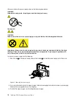
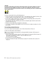
DANGER

Hazardous moving parts. Keep fingers and other body parts adway.

Statement 8

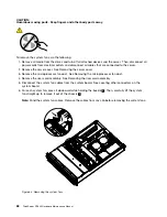
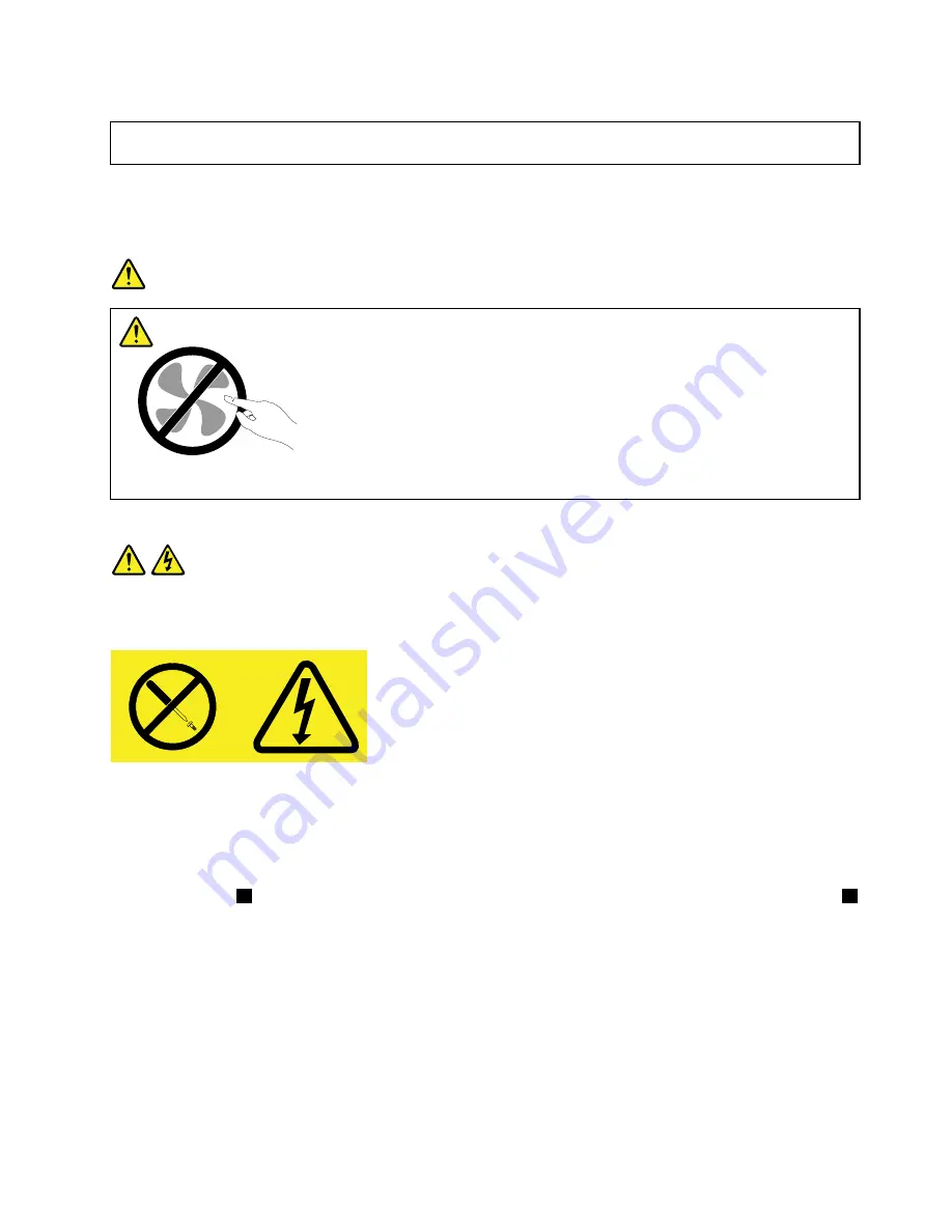
CAUTION:
Never remove the cover on a power supply or any part that has the following label attached.

Hazardous voltage, current, and energy levels are present inside any component that has this label
attached. There are no serviceable parts inside these components. If you suspect a problem with
one of these parts, contact a service technician.

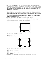
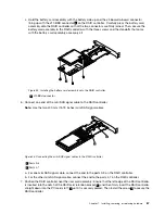
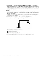
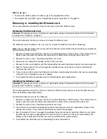
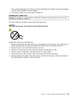
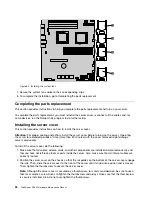
To install a power supply, do the following:

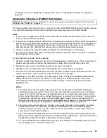
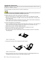
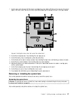
1. Press the tab

1

on the bezel that covers the bay of the power supply and insert a finger into the hole

2

in the middle of the bezel. Then, pull the bezel out to remove it.

Chapter 7

.

Installing, removing, or replacing hardware

77

Summary of Contents for ThinkServer 1045

Page 1: ...ThinkServer RD240 Hardware Maintenance Manual Machine Types 1045 1046 1047 and 1048 ...

Page 2: ... product Safety information on page iii Appendix C Notices on page 137 Seventh Edition March 2012 Copyright Lenovo 2010 2012 LIMITED AND RESTRICTED RIGHTS NOTICE If data or software is delivered pursuant a General Services Administration GSA contract use reproduction or disclosure is subject to restrictions set forth in Contract No GS 35F 05925 ...

Page 3: ...e system board 30 Locating connectors on the backplane 33 Chapter 7 Installing removing or replacing hardware 35 Guidelines 35 Precautions 35 Handling static sensitive devices 36 System reliability guidelines 36 Working inside the server with the power on 37 Removing the server cover 37 Installing removing or replacing optional hardware devices 38 Installing or removing a memory module 38 Removing...

Page 4: ... the ThinkServer EasyManage program 129 Appendix A RAID battery card assembly 131 Specifications 131 Battery life and data retention time 131 Appendix B Getting information help and service 133 Information resources 133 Using the documentation 133 ThinkServer Web site 133 Lenovo Support Web site 133 Help and service 134 Before you call 134 Calling for service 134 Using other services 135 Purchasin...

Page 5: ...n käyttöä Avant d utiliser le produit veillez à bien lire et comprendre les instructions de sécurité multilingues figurant sur le DVD de documentation fourni avec le produit Πριν χρησιμοποιήσετε το προϊόν βεβαιωθείτε ότι έχετε διαβάσει και κατανοήσει τις οδηγίες ασφάλειας οι οποίες είναι διαθέσιμες σε διάφορες γλώσσες στο DVD τεκμηρίωσης που συνοδεύει το προϊόν Vor Verwendung des Produkts sollten ...

Page 6: ...umentacijo ki ste ga prejeli skupaj z izdelkom Antes de utilizar el producto asegúrese de leer y comprender las instrucciones de seguridad multilingües del DVD de documentación que se proporciona con el producto Var noga med att läsa säkerhetsinstruktionerna på dokumentations DVD skivan som följer med produkten innan du börjar använda produkten 使用本產品之前 請務必閱讀並瞭解產品隨附的文件 DVD 上的多國語言版本安全資訊 Bu ürünü kul...

Page 7: ...d configuration procedures Connect and disconnect cables as described in the following table when installing moving or opening covers on this product or attached devices To connect To disconnect 1 Turn everything OFF 2 First attach all cables to devices 3 Attach signal cables to connectors 4 Attach power cords to outlet 5 Turn devices ON 1 Turn everything OFF 2 First remove power cords from outlet...

Page 8: ...A or Class 3B laser diode Note the following Laser radiation when open Do not stare into the beam do not view directly with optical instruments and avoid direct exposure to the beam Statement 4 18 kg 39 7 lb 32 kg 70 5 lb 55 kg 121 2 lb 32 kg 70 5 lb 55 kg 121 2 lb 100 kg 220 5 lb CAUTION Use safe practices when lifting Statement 5 CAUTION The power control button on the device and the power switc...

Page 9: ... the device Statement 8 CAUTION Never remove the cover on a power supply or any part that has the following label attached Hazardous voltage current and energy levels are present inside any component that has this label attached There are no serviceable parts inside these components If you suspect a problem with one of these parts contact a service technician Statement 9 CAUTION To avoid personal ...

Page 10: ...ecured properly to avoid tipping when the server unit is extended Statement 14 CAUTION Some accessory or option board outputs exceed Class 2 or limited power source limits and must be installed with appropriate interconnecting cabling in accordance with the national electric code Statement 15 CAUTION The power control button on the device does not turn off the electrical current supplied to the de...

Page 11: ...es to exceed a safe level 60 V direct current The branch circuit overcurrent protection must be rated in accordance with local building codes Use 16 American Wire Gauge AWG or 1 3 mm2 copper conductor only not exceeding 3 meters in length Torque the wiring terminal screws to 12 inch pounds 1 4 newton meters Incorporate a readily available approved and rated disconnect device in the field wiring St...

Page 12: ...s a lithium ion battery To avoid possible explosion do not burn the battery Exchange it only with the Lenovo approved part Recycle or discard the battery as instructed by local regulations x ThinkServer RD240 Hardware Maintenance Manual ...

Page 13: ... request you will be charged for the installation Optional service CRUs Although dealing with Optional service CRUs requires some technical skills Optional service CRUs are safe for customers to replace You may install an Optional service CRU yourself or request Lenovo to install it at no additional charge under the type of warranty service that is designated for the server FRUs FRUs must be repla...

Page 14: ...e documentation DVD insert the DVD into the optical drive The DVD is AutoPlay enabled and starts automatically in most environments If the DVD fails to start or if you are using a Linux operating system open the launch htm file located in the root directory of the DVD Note Lenovo maintains pages on the World Wide Web where you can get the latest technical information and download documentation or ...

Page 15: ...ment is in English only Document only for trained service personnel The following document is intended only for trained service personnel of Lenovo Hardware Maintenance Manual This document provides diagnostic information parts listing and replacement procedures for all Field Replaceable Units FRUs parts replaced by trained service personnel as well as all CRUs This document is updated frequently ...

Page 16: ...4 ThinkServer RD240 Hardware Maintenance Manual ...

Page 17: ...ation DVD Connect the Ethernet cable and power cord Rear view on page 27 Turn on the server to verify operation Turning on the server on page 91 Review the BIOS settings and customize as needed Starting the Setup Utility program on page 112 Configure RAID onboard SATA RAID or the installed SAS RAID adapter RAID controllers on page 120 Check for firmware updates Using the EasyUpdate Firmware Update...

Page 18: ...6 ThinkServer RD240 Hardware Maintenance Manual ...

Page 19: ...ual inline memory modules DIMMs High performance graphics controller The server comes with an onboard high performance graphics controller that supports high resolutions and includes many performance enhancing features for the operating system environment Redundant connection The two onboard network interface controllers NIC provide a failover capability to a redundant Ethernet connection If a pro...

Page 20: ...nt and four rear Two RJ 45 Ethernet connectors One serial port One Video Graphics Array VGA monitor connector Environment Air temperature Server on 10 C to 35 C 50 F to 95 F altitude 0 to 914 4 m 3 000 ft Server off 10 C to 43 C 50 F to 109 4 F maximum altitude 2 133 6 m 7 000 ft Shipping 40 C to 60 C 104 F to 140 F Humidity Server on up to 80 non condensing Server off up to 80 non condensing Ship...

Page 21: ...Linux operating systems and device drivers on your server The EasyStartup program is provided with your server on the ThinkServer EasyStartup DVD The DVD is self starting bootable The user guide for the EasyStartup program is on the DVD and can be accessed directly from the program interface For additional information see Using the ThinkServer EasyStartup program on page 121 EasyManage The ThinkSe...

Page 22: ...10 ThinkServer RD240 Hardware Maintenance Manual ...

Page 23: ...n setup system configuration and RAID configuration Built in monitoring for fan temperature and voltage Cooling fans with speed sensing capability ECC DDR3 SDRAM with Serial Presence Detect SPD Error codes and messages to help you identify problems Generating error logs for the power on self test POST failures Hot swap SAS hard disk drives Integrated Ethernet controllers Intelligent Platform Manag...

Page 24: ...12 ThinkServer RD240 Hardware Maintenance Manual ...

Page 25: ...ed See the parts listing in Chapter 8 Parts listing RD240 Types 1045 1046 1047 and 1048 on page 93 to determine which components are customer replaceable units CRUs and which components are field replaceable units FRUs If an action step is preceded by Trained service technician only that step must be performed only by a trained service technician Symptom Action The DVD drive is not recognized 1 Ma...

Page 26: ...working or a similar problem has occurred If the part is a CRU replace it If the part is a FRU the part must be replaced by a trained service technician Hard disk drive problems Follow the suggested actions in the order in which they are listed in the Action column until the problem is solved See the parts listing in Chapter 8 Parts listing RD240 Types 1045 1046 1047 and 1048 on page 93 to determi...

Page 27: ... which components are customer replaceable units CRUs and which components are field replaceable units FRUs If an action step is preceded by Trained service technician only that step must be performed only by a trained service technician Symptom Action All or some keys on the keyboard do not work 1 Make sure that The keyboard cable is securely connected The server and the monitor are turned on 2 T...

Page 28: ...unt of installed physical memory 1 Make sure that No error LEDs are lit on the operator information panel or on the DIMM Memory mirroring does not account for the discrepancy The memory modules are seated correctly You have installed the correct type of memory If you changed the memory you updated the memory configuration in the Setup Utility program All banks of memory are enabled The server migh...

Page 29: ...eceded by Trained service technician only that step must be performed only by a trained service technician Symptom Action The server emits a continuous beep during the POST indicating that the startup boot microprocessor is not working correctly 1 Make sure that the server supports all the microprocessors and that the microprocessors match in speed and cache size 2 Trained service technician only ...

Page 30: ... correctly No POST errors are generated when the server is turned on 3 Make sure that the correct server is controlling the monitor if applicable 4 See Solving undetermined problems on page 23 The monitor has screen jitter or the screen image is wavy unreadable rolling or distorted 1 If the monitor self tests show that the monitor is working correctly consider the location of the monitor Magnetic ...

Page 31: ...e that you just installed A Lenovo optional device that used to work does not work now 1 Make sure that all of the hardware and cable connections for the device are secure 2 If the device comes with test instructions use those instructions to test the device 3 If the failing device is a SCSI device make sure that The cables for all external SCSI devices are connected correctly The last device in e...

Page 32: ...y do not indicate a problem The microprocessors are installed in the correct sequence 3 Reseat the following components a DIMMs b Trained service technician only Power switch connector c Trained service technician only Power backplane 4 Replace the following components one at a time in the order shown restarting the server each time a DIMMs b Trained service technician only Power switch connector ...

Page 33: ...tion The number of serial ports that are identified by the operating system is less than the number of installed serial ports 1 Make sure that Each port is assigned a unique address in the Setup Utility program and none of the serial ports is disabled The serial port adapter if one is present is seated correctly 2 Reseat the serial port adapter 3 Replace the serial port adapter A serial device doe...

Page 34: ...ed service technician Symptom Action A USB device does not work 1 Make sure that The correct USB device driver is installed The operating system supports USB devices A standard PS 2 keyboard or mouse is not connected to the server If it is a USB keyboard or mouse will not work during the POST 2 Make sure that the USB configuration optional devices are set correctly in the Setup Utility program 3 I...

Page 35: ...om the hub If the LED is off there might be a defective connector or cable or a problem with the hub The Ethernet transmit receive activity LED is lit when the Ethernet controller sends or receives data over the Ethernet network If the Ethernet transmit receive activity LED is off make sure that the hub and network are operating and that the correct device drivers are installed Check the LAN activ...

Page 36: ...log This log contains the three most recent error codes and messages that were generated during the POST System event log This log contains all the POST and system management interrupt SMI events You can view the system event log through the Setup Utility program and through the as the IPMI event log The system event log is limited in size When it is full new entries will not overwrite existing en...

Page 37: ...arning messages do not require immediate action they indicate possible problems such as when the recommended maximum ambient temperature is exceeded Error Error messages might require action they indicate system errors such as when a fan is not detected Each message contains date and time information and it indicates the source of the message POST Diagnostic LEDs on the front control panel Identif...

Page 38: ...26 ThinkServer RD240 Hardware Maintenance Manual ...

Page 39: ...rts on the front of the server Figure 1 Front view of the server with eight hard disk drives and an optical drive 1 Left handle of the chassis 4 Optical drive 2 3 5 inch hard disk drive bay 5 Front control panel see Front control panel on page 28 3 3 5 inch hard disk drive dummy bay Rear view Rear view of the server shows the locations of the connectors and parts on the rear of the server Figure 2...

Page 40: ...anel helps you identify the connectors controls and LEDs on the front control panel of your server Figure 3 Front control panel 1 ID button and LED 4 Ethernet 2 status LED 2 System status LED 5 Power button and LED 3 Ethernet 1 status LED The following table describes the meaning of the LEDs on the front control panel Table 4 Front control panel LEDs LED State Color Description On Blue ID is on ID...

Page 41: ...68E SAS RAID adapter and external 8708ELP SAS RAID adapter configurations Description Hard disk drive status LED 1 Hard disk drive status LED 2 Hard disk drive is not present Off Off Hard disk drive is present but is not active Off Green for SATA hard disk drives the status is Off Hard disk drive is present and active Off Blinking green Server is in the process of locating the hard disk drive Blin...

Page 42: ...e depending on the model 3 Microprocessor and heat sink 8 3 5 inch hard disk drive dummy bay 4 Memory modules 9 3 5 inch hard disk drive 5 Power supply assembly 10 Left handle of the chassis Locating parts on the system board Figure 5 Locating major parts on the system board on page 31 and Figure 6 Locating other connectors on the system board on page 32 show the locations of the parts on the syst...

Page 43: ...AS 1 bottom SAS 0 7 24 pin power connector for the system board 20 SAS connectors top SAS 3 bottom SAS 2 8 Microprocessor CPU0 21 SAS connectors top SAS 5 bottom SAS 4 9 Memory slot CPU0 DIMM CHA1 22 SAS connectors top SAS 7 bottom SAS 6 10 Memory slot CPU0 DIMM CHA0 23 Onboard 1068E SAS RAID controller 11 Memory slot CPU0 DIMM CHB0 24 System board battery 12 Memory slot CPU0 DIMM CHC0 25 PCI Expr...

Page 44: ...ins 1 2 during the normal operation of the system JP1 Clear CMOS Pins 2 3 If the jumper is placed on pins 2 3 when the jumper is moved back to the default positions and at the next startup the settings of CMOS will be cleared automatically Pins 1 2 The default position at which the jumper is placed on pins 1 2 during the normal operation of the system The onboard SAS controller is Enabled JP7 Set ...

Page 45: ...ane connector locations shows the connector locations on the backplane Figure 7 Backplane connector locations 1 Mini SAS signal connector 2 2 Power connector 3 Mini SAS signal connector 1 Chapter 6 Locating parts controls LEDs and connectors 33 ...

Page 46: ...34 ThinkServer RD240 Hardware Maintenance Manual ...

Page 47: ...addressed and that your server is ready to function at maximum levels of performance To download firmware updates for your server do the following 1 Go to http www lenovo com support 2 Click Download Drivers Software and follow the instructions on the Web page to download firmware updates for your server See Updating the firmware on page 128 for more information Before you install optional hardwar...

Page 48: ...frame Do not touch solder joints pins or exposed circuitry Prevent others from touching the parts and other computer components Before you replace a new part touch the static protective package containing the new part to a metal expansion slot cover or other unpainted metal surface on the server for at least two seconds This reduces static electricity from the package and your body Remove the new ...

Page 49: ...cuff links while you are working inside the server Do not allow your necktie or scarf to hang inside the server Remove jewelry such as bracelets necklaces rings and loose fitting wrist watches Remove items from your shirt pocket such as pens and pencils These items might fall into the server as you lean over it Avoid dropping any metallic objects into the server such as paper clips hairpins and sc...

Page 50: ...to install or remove a memory module For a list of the supported memory modules for your server go to http www lenovo com thinkserver On the ThinkServer systems page click Products Options ThinkServer Memory Memory module installation rules Your server has eight memory slots for installing or replacing DDR3 SDRAM DIMMs that provide up to a maximum of 64 GB of system memory The following tables pro...

Page 51: ... sequence rather than the sequence listed above if you want to use the Channel Mirroring Mode 1 Pair 1 install a DIMM on CPU0 DIMM CHA0 and then install a DIMM on CPU0 DIMM CHB0 2 Pair 2 install a DIMM on CPU1 DIMM CHA0 and then install a DIMM on CPU1 DIMM CHB0 Installing a memory module Attention Do not open your server or attempt any repair before reading and understanding the Safety information...

Page 52: ... has not been correctly installed Open the retaining clips remove the memory module and then reinstall it into the slot Figure 10 Installing the memory module 7 To complete the installation go to Completing the parts replacement on page 90 Removing a memory module Attention Do not open your server or attempt any repair before reading and understanding the Safety information on page iii and Guideli...

Page 53: ...he cables and other equipment that is specified in the documentation that comes with the drive Select the drive bay in which you want to install the drive Check the instructions that come with the drive to see whether you have to set any switches or jumpers on the drive If you are installing a SAS device be sure to set the SAS ID for that device The EMI integrity and cooling of the server are prot...

Page 54: ...e server cover 3 There is one screw on each side and two screws on the top Remove the four screws that secure the drive access panel 1 Slide the drive access panel back and lift it to remove it 2 Figure 12 Removing the drive access panel 4 Disconnect the power cable and the signal cable from the rear of the optical drive 5 Remove the retaining screw on the rear bracket of the optical drive 42 Thin...

Page 55: ...al drive cage with the optical drive Figure 14 Sliding out the optical drive cage with the optical drive 7 Remove the two retaining screws that secure the optical drive in the cage Then slide the optical drive out of the cage Chapter 7 Installing removing or replacing hardware 43 ...

Page 56: ...rtant Before you install optional hardware devices make sure that the server is working correctly If the server is not working correctly refer toDiagnostics for your server for detailed diagnostic information To obtain the publication go to http www lenovo com support To install the optical drive do the following 1 If you are replacing the optical drive make sure that You have all the cables and o...

Page 57: ...ollowing Laser radiation when open Do not stare into the beam do not view directly with optical instruments and avoid direct exposure to the beam Class 1 Laser Product Laser Klasse 1 Laser Klass 1 Luokan 1 Laserlaite Appareil A Laser de Classe 1 2 Remove all media from the drives and turn off all attached devices and the server Then disconnect all power cords from electrical outlets and disconnect...

Page 58: ...Figure 16 Removing the drive access panel 5 Remove the retaining screw on the rear bracket of the optical drive 46 ThinkServer RD240 Hardware Maintenance Manual ...

Page 59: ... the optical drive cage retaining screw 6 Slide out the optical drive cage Figure 18 Sliding out the optical drive cage 7 Remove the bezel of the optical drive cage Chapter 7 Installing removing or replacing hardware 47 ...

Page 60: ...lace it on a static protective surface 9 Follow the instructions that come with the optical drive to set jumpers or switches if there are any 10 Pay attention to the up and down position of the optical drive and slide the optical drive into place Figure 20 Sliding the optical drive into the drive cage 11 Install the two retaining screws to secure the optical drive in the cage 48 ThinkServer RD240 ...

Page 61: ...e the cage with the optical drive into place Figure 22 Sliding the cage with the optical drive into place 13 Install the retaining screw to the rear of the cage to secure the optical drive cage in place Chapter 7 Installing removing or replacing hardware 49 ...

Page 62: ...idelines on page 35 This section provides instructions on how to remove a hot swap hard disk drive This section applies only to server models that have hot swap hard disk drives installed Attention To maintain proper system cooling do not operate the server for more than 10 minutes without either a drive or a filler panel installed in each drive bay To remove a hot swap hard disk drive do the foll...

Page 63: ... without either a drive or a filler panel installed in each drive bay To install a hot swap hard disk drive do the following Note You do not have to turn off the server for the installation of a hot swap hard disk drive 1 If you are replacing a hot swap hard disk drive remove the old one first See Removing a hot swap hard disk drive on page 50 If you are installing a hot swap hard disk drive in a ...

Page 64: ...n provides instructions on how to remove or install the riser card assembly Removing the riser card assembly Attention Do not open your server or attempt any repair before reading and understanding the Safety information on page iii and Guidelines on page 35 This section provides instructions on how to remove the riser card assembly with PCI card s installed To remove the riser card assembly do th...

Page 65: ...ng each side of the riser card a small and equal amount until it is completely removed from the slot Figure 26 Removing the riser card assembly What to do next To work with another piece of hardware go to the appropriate section To complete the removal procedure go to Completing the parts replacement on page 90 Installing the riser card assembly Attention Do not open your server or attempt any rep...

Page 66: ...r card from the static protective package 4 Position the riser card assembly in place so that you can press the riser card straight down into the PCI card slot on the system board See Locating parts on the system board Then install the two screws to secure the riser card assembly in place You might need a screw driver to make sure that the screws are firmly tightened and the riser card assembly is...

Page 67: ...l cables that are connected to the server 2 Remove the server cover See Removing the server cover on page 37 3 Remove the riser card assembly See Removing the riser card assembly on page 52 4 Locate the PCI card slot 2 2 on the riser card assembly Then remove the screw on the side that secures the metal slot cover Notes There are three PCI card slots on the riser card assembly as shown in the illu...

Page 68: ...ur server or attempt any repair before reading and understanding the Safety information on page iii and Guidelines on page 35 This section provides instructions on how to remove a PCI card Notes Depending on the server model your server might look different from the illustration in this section Use any documentation that comes with the PCI card and follow those instructions in addition to the inst...

Page 69: ...he failing hardware devices If you are replacing a hardware device perform the removal procedure and then perform the installation procedure for the hardware device that you want to replace Removing or installing the system board battery This section provides instructions on how to remove or install the system board battery Removing the system board battery Attention Do not open your server or att...

Page 70: ...er and reset the system date and time To avoid possible danger read and follow the following safety statement Statement 2 CAUTION When replacing the lithium battery use only Part Number 33F8354 or an equivalent type battery recommended by the manufacturer If your system has a module containing a lithium battery replace it only with the same module type made by the same manufacturer The battery con...

Page 71: ...ource from the server you lose the ability to view the LEDs because the LEDs are not lit when the power source is removed Before you disconnect the power source make a note of which LEDs are lit including the LEDs that are lit on the front control panel The RAID controller is installed on the riser card assembly To remove the RAID controller do the following 1 Remove all media from the drives and ...

Page 72: ...assembly before you install or remove the RAID controller For instructions on how to install the RAID card retention bracket refer to the Important Information about the RAID Card Retention Bracket PN 0A91937 that comes with your RAID controller option package 3 The RAID card retention bracket might look different from the illustrations in this section 4 Use any documentation that comes with the R...

Page 73: ...he appropriate support Web sites for the latest updates for your basic input output system BIOS code utility programs device drivers and other software applications Follow the instructions provided by your Service Provider to download and install updates d It is recommended that you replace the battery pack on the battery card assembly annually or after 500 recharging cycles whichever comes first ...

Page 74: ...ackside of the battery card assembly Figure 34 Bottom view of the battery card assembly 1 J3 battery pack harness connector 2 J1 connector 3 J2 board to board connector Figure 35 Top view of the battery card assembly 1 Battery pack harness b With the front side up place the RAID controller on a flat clean static free surface 62 ThinkServer RD240 Hardware Maintenance Manual ...

Page 75: ...D controller near the riser card assembly Ensure that the left edge of the RAID controller is inserted into the notch of the RAID card retention bracket 1 and then firmly insert the RAID controller straight down into the PCI card slot 1 2 until it is securely seated Then install the screw 3 to secure the RAID controller Figure 37 Installing the RAID controller into the PCI card slot 1 on the riser...

Page 76: ...er mini SAS signal cable connect one end to the ports 4 7 on the RAID controller Then connect the other end to the mini SAS signal connector 1 on the backplane Figure 39 Mini SAS signal connectors on the backplane What to do next To work with another piece of hardware go to the appropriate section To complete the installation go to Completing the parts replacement on page 90 To reduce fan noise th...

Page 77: ...ive package that contains the RAID controller to any unpainted surface on the outside of the server Then remove the RAID controller from the package 5 Depending on your RAID controller you might need to install a ThinkServer 8708EM2 RAID Adapter Battery hereafter referred to as the battery card assembly on the RAID controller The battery card assembly mounts directly to the RAID controller through...

Page 78: ...d assembly The battery in the battery card assembly must recharge for at least six hours during fast charge under normal operating conditions To install the battery card assembly onto the RAID controller do the following a Note the top view and bottom view of the battery card assembly Then insert the battery pack harness connector into the J4 battery pack harness connector on the backside of the b...

Page 79: ...able to the RAID controller Note Use the two 400 mm 15 75 inches mini SAS signal cables Figure 43 Connecting the mini SAS signal cables to the RAID controller 1 Ports 0 3 2 Ports 4 7 a For one mini SAS signal cable connect the end to the ports 0 3 on the RAID controller b For the other mini SAS signal cable connect the end to the ports 4 7 on the RAID controller 7 Position the RAID controller near...

Page 80: ...e system board 9 Connect the other end of the two 400 mm 15 75 inches mini SAS signal cables to the backplane of your server Figure 45 Mini SAS signal connectors on the backplane a For one mini SAS signal cable connect the other end to the mini SAS signal connector 2 on the backplane b For the other SAS signal cable connect the other end to the mini SAS signal connector 1 on the backplane What to ...

Page 81: ...card assembly See Removing the riser card assembly on page 52 4 Touch the static protective package that contains the RAID controller to any unpainted surface on the outside of the server Then remove the RAID controller from the package 5 Depending on your RAID controller you might need to install a ThinkServer RAID 700 Battery hereafter referred to as the battery card assembly on the RAID control...

Page 82: ...lot center the Phillips head screw driver to avoid damaging the screw head and do not over tighten the screws as you might damage the battery card assembly The battery in the battery card assembly must recharge for at least six hours during fast charge under normal operating conditions To install the battery card assembly onto the RAID controller do the following a Note the bottom view of the batt...

Page 83: ...th the battery card assembly accessory kit Figure 47 Installing the battery card assembly onto the RAID controller 1 J6B1 BBU connector 6 Connect the mini SAS signal cables to the RAID controller Note Use the 400 mm 15 75 inches mini SAS signal cables Figure 48 Connecting the mini SAS signal cables to the RAID controller 1 Ports 0 3 2 Ports 4 7 a For one mini SAS signal cable connect the end to th...

Page 84: ...wn in the illustration The PCI card slot 1 2 is for RAID cards only For more information about the PCI card slots see Installing a PCI card on page 55 8 Install the riser card with the RAID controller into an appropriate PCI card slot on the system board 9 Connect the other end of the two 400 mm 15 75 inches mini SAS signal cables to the backplane of your server Figure 50 Mini SAS signal cable con...

Page 85: ... Ethernet card from the riser card 6 If you are instructed to return the Ethernet card follow all packaging instructions and use any packaging materials that are supplied to you for shipping 7 To complete the removal procedure go to Completing the parts replacement Installing the Ethernet card Attention Do not open your server or attempt any repair before reading and understanding the Safety infor...

Page 86: ...oftware automatically Recommended and click Next to continue 8 Follow the instructions on the screen Removing or installing the microprocessor fan duct This section provides instructions on how to remove or install the microprocessor fan duct Removing the microprocessor fan duct Attention Do not open your server or attempt any repair before reading and understanding the Safety information on page ...

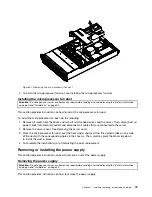
Page 87: ...l cables that are connected to the server 2 Remove the server cover See Removing the server cover 3 Place the microprocessor fan duct over the heat sink s and insert the three plastic tabs on one side of the duct with the corresponding holes in the chassis Then carefully pivot the other side down to install the duct in place 4 To complete the installation go to Completing the parts replacement Rem...

Page 88: ... serviceable parts inside these components If you suspect a problem with one of these parts contact a service technician To remove a power supply do the following 1 Press the tab 1 of the power supply and pull the handle 2 to slide the power supply out of the server Figure 52 Removing the power supply 2 If you are instructed to return the power supply follow all packaging instructions and use any ...

Page 89: ...ON Never remove the cover on a power supply or any part that has the following label attached Hazardous voltage current and energy levels are present inside any component that has this label attached There are no serviceable parts inside these components If you suspect a problem with one of these parts contact a service technician To install a power supply do the following 1 Press the tab 1 on the...

Page 90: ...w to remove or install the heat sink Removing the heat sink Attention Do not open your server or attempt any repair before reading and understanding the Safety information on page iii and Guidelines on page 35 This section provides instructions on how to remove the heat sink CAUTION The heat sink might be very hot Turn off the server and wait three to five minutes to let the server cool before rem...

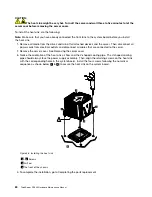
Page 91: ...eat sink out of the chassis Figure 55 Removing the heat sink 1 4 Screws 5 Air flow 6 The front of the chassis 5 If you are instructed to return the heat sink follow all packaging instructions and use any packaging materials that are supplied to you for shipping 6 To install the heat sink see Installing the heat sink Installing the heat sink Attention Do not open your server or attempt any repair b...

Page 92: ...les that are connected to the server 2 Remove the server cover See Removing the server cover 3 Notice the orientation of the heat sink air flow and the V shaped cooling pipe The V shaped cooling pipe should always face the power supply assembly Then align the retaining screws on the heat sink with the corresponding holes in the system board Install the four screws following the numerical sequence ...

Page 93: ...ver Then disconnect all power cords from electrical outlets and disconnect all cables that are connected to the server 2 Remove the server cover See Removing the server cover 3 Remove the microprocessor fan duct See Removing the microprocessor fan duct 4 Remove the heat sink See Removing the heat sink 5 Lift the small handle and open the retainer to access the microprocessor Then carefully lift th...

Page 94: ...all another microprocessor into the CPU1 socket if you want to install two microprocessors To install the microprocessor do the following 1 Remove all media from the drives and turn off all attached devices and the server Then disconnect all power cords from electrical outlets and disconnect all cables that are connected to the server 2 Remove the server cover See Removing the server cover 3 Remov...

Page 95: ...of the new microprocessor 9 Hold the new microprocessor by the edges and align the notches 1 on it with the tabs 2 in the microprocessor socket Then install the microprocessor into the socket Figure 61 Installing the microprocessor 10 To complete the installation go to Completing the parts replacement Chapter 7 Installing removing or replacing hardware 83 ...

Page 96: ...es and the server Then disconnect all power cords from electrical outlets and disconnect all cables that are connected to the server 2 Remove the server cover See Removing the server cover 3 Remove the microprocessor fan duct See Removing the microprocessor fan duct 4 Remove the riser card assembly See Removing the riser card assembly 5 Remove the heat sink and a memory module See Removing the hea...

Page 97: ...or socket cover removed from the new system board on the failing system board To install a microprocessor socket cover do the following a Release the lever securing the microprocessor retainer and open the retainer to access the microprocessor b Grasp the microprocessor on the sides and lift it straight up and out of the socket Do not touch the contacts on the microprocessor socket c Align the not...

Page 98: ...for shipping 15 To install a new system board see Installing the system board Installing the system board Attention Do not open your server or attempt any repair before reading and understanding the Safety information on page iii and Guidelines on page 35 This section provides instructions on how to install a new system board after a failing system board is removed CAUTION The heat sink and microp...

Page 99: ...er card assembly 6 Note the location of all cable connections on the system board and connect all cables Locating parts on the system board 7 Install the microprocessor fan duct SeeInstalling the microprocessor fan duct 8 Install the server cover See Installing the server cover 9 To complete the installation go to Completing the parts replacement Removing or installing the system fans This section...

Page 100: ...ve the microprocessor fan duct See Removing the microprocessor fan duct 4 Remove the riser card assembly See Removing the riser card assembly 5 Disconnect the system fan cables from the system board See Locating other connectors on the system board 6 For each system fan press it downward while holding the buckle 1 Then carefully lift the system fan straight up to remove it out of the chassis 2 Not...

Page 101: ...nstall the system fans do the following 1 Remove all media from the drives and turn off all attached devices and the server Then disconnect all power cords from electrical outlets and disconnect all cables that are connected to the server 2 Remove the server cover See Removing the server cover 3 Remove the microprocessor fan duct See Removing the microprocessor fan duct 4 Remove the riser card ass...

Page 102: ...han 30 minutes with the cover removed might damage server components To install the server cover do the following 1 Make sure that all cables add on cards and other components are installed and seated correctly and that you have not left loose tools or parts inside the server Also make sure that all internal cables are correctly routed 2 Position the server cover on the chassis so that the rail gu...

Page 103: ...anel on page 28 Updating the server configuration When you turn on the server for the first time after you add or remove a device you might receive a message saying that the configuration has been changed The Setup Utility program starts automatically so that you can save the new configuration settings For more information see Chapter 9 Configuring the server on page 111 Some optional devices have...

Page 104: ...g you can press and hold the power button for more than four seconds to turn off the server The server can be turned off by the Shutdown on LAN feature The integrated management module IMM can turn off the server as an automatic response to a critical system failure Connecting external devices If you install a supported optional adapter you can attach external devices to the server To attach an ex...

Page 105: ... To check for an updated parts listing on the Web complete the following steps 1 Go to http www lenovo com support 2 Click Download Drivers ThinkServer and then follow the instructions on the Web page to download firmware updates for your server 1 System fan 2 Riser card assembly 3 Heat sink 4 DIMM 5 Power supply 6 Microprocessor 7 System board Copyright Lenovo 2010 2012 93 ...

Page 106: ...ll models 46U3527 2 Riser card assembly models CTO all models 46U3605 3 Heat sink 80 95 W models CTO all models 46U3277 4 Memory DIMM 2 GB DDR3 RDIMM 1333 MHz models CTO 11G 46U3442 4 Memory DIMM 4 GB DDR3 RDIMM 1333 MHz models CTO 12U 46U3443 4 Memory DIMM 8 GB DDR3 1333 RDIMM models CTO 46U3419 5 Power supply 750 Watt redunant power supply unit PSU models CTO all models 46U3278 5 Power supply po...

Page 107: ...3X3649 6 Microprocessor Intel Xeon X5675 6 core 3 06 GHz 6 4 QPI 12 MB cache DDR3 1333 95 W models CTO 03X3650 6 Microprocessor Intel Xeon X5672 quad core 3 2 GHz 6 4 QPI 12 MB cache DDR3 1333 95 W models CTO 03X3651 6 Microprocessor Intel Xeon E5507 quad core 2 26 GHz 4 8 QPI 4 MB cache DDR3 800 80 W models CTO 71Y9031 7 System board Mitac S7007 SAS MB with iKVM models CTO 11G 12U 46U3453 7 Syste...

Page 108: ...t models CTO all models 46U3530 Screw kit models CTO all models 46U3531 LSI MegaRAID 8708E SAS RAID 256 MB models CTO 12U 46U3224 LSI 1078MP 8708E battery models CTO 46U3357 LSI 3801E SAS HBA models CTO 46U3547 Emulex LPe1150 4 Gb models CTO 46U3314 Emulex LPe111 E 4 Gb models CTO 46U3315 Intel PRO 1000PT dual ports Ethernet card models CTO 67Y1430 LSI 8708EM2 8 ports 256 MB SAS RAID Card models C...

Page 109: ...e 2 66 GHz 5 86 QPI 12 MB cache DDR3 1066 80 W models CTO 14U 15G 71Y9045 6 Microprocessor Intel Xeon X5660 6 core 2 80 GHz 6 4 QPI 12 MB cache DDR3 1333 95 W models CTO 71Y9041 6 Microprocessor Intel Xeon X5650 6 core 2 66 GHz 6 4 QPI 12 MB cache DDR3 1333 95 W models CTO 16G 1DU 1DG 71Y9043 6 Microprocessor Intel Xeon E5630 quad core 2 53 GHz 5 86 QPI 12 MB cache DDR3 1066 80 W models CTO 71Y904...

Page 110: ...B SAS 15000 rpm 6 Gb s 32 MB cache 3 5 models CTO 46U3439 9 Hard disk drive 2TB SATA Enterprise 7200 rpm 3 Gb s 32 MB cache 3 5 models CTO 46U3400 9 Hard disk drive 600 GB SAS 15000 rpm 3 Gb s 32 MB cache 3 5 models CTO 03X3623 9 Hard disk drive 450 GB SAS 15000 rpm 6 Gb s 32 MB cache 3 5 models CTO 46U3440 440 mm MiniSAS cable models CTO all models 46U3519 550 mm MiniSAS 4single port cable models...

Page 111: ...models 46U3277 4 Memory DIMM 2 GB DDR3 RDIMM 1333 MHz models CTO 11U 11G 12U 12G 46U3442 4 Memory DIMM 4 GB DDR3 RDIMM 1333 MHz models CTO 46U3443 4 Memory DIMM 8 GB DDR3 1333 RDIMM models CTO 46U3419 5 Power supply 750 Watt Redunant power supply unit PSU models CTO 46U3278 5 Power supply Power Distribution Module models CTO all models 90Y1394 6 Microprocessor Intel Xeon E5503 dual core 2 00 GHz 4...

Page 112: ... DDR3 1066 80 W models CTO 03X3649 6 Microprocessor Intel Xeon X5675 6 core 3 06 GHz 6 4 QPI 12 MB cache DDR3 1333 95 W models CTO 03X3650 6 Microprocessor Intel Xeon X5672 quad core 3 2 GHz 6 4 QPI 12 MB cache DDR3 1333 95 W models CTO 03X3651 6 Microprocessor Intel Xeon E5507 quad core 2 26 GHz 4 8 QPI 4 MBcache DDR3 800 80W models CTO 71Y9031 7 System board Mitac S7007 SAS MB models CTO 11U 11G...

Page 113: ...s 46U3531 LSI MegaRAID 8708E SAS RAID 256 MB models CTO 46U3224 LSI 1078MP 8708E battery models CTO 46U3357 LSI 3801E SAS HBA models CTO 46U3547 Emulex LPe1150 4Gb models CTO 46U3314 Emulex LPe111 E 4Gb models CTO 46U3315 LSI 8708EM2 8ports 256 MB SAS RAID card models CTO 03X3619 LSI iBBU06 battery unit for 8708EM2 models CTO 03X3620 ThinkServer RAID 700 Adapter models CTO 03X3617 ThinkServer RAID...

Page 114: ... 80 GHz 6 4 QPI 12 MB cache DDR3 1333 95 W models CTO 71Y9041 6 Microprocessor Intel Xeon X5650 6 core 2 66 GHz 6 4 QPI 12 MB Cache DDR3 1333 95 W models CTO 13U 71Y9043 6 Microprocessor Intel Xeon E5630 quad core 2 53 GHz 5 86 QPI 12 MB cache DDR3 1066 80 W models CTO 71Y9047 6 Microprocessor Intel Xeon E5620 quad core 2 40 GHz 5 86 QPI 12 MB cache DDR3 1066 80 W models CTO 71Y9049 6 Microprocess...

Page 115: ...dels CTO 46U3400 9 Hard disk drive 600 GB SAS 15000 rpm 3 Gb s 32 MB cache 3 5 models CTO 03X3623 440 mm MiniSAS cable models CTO all models 46U3519 550mm MiniSAS 4single port cable models CTO all models 46U3520 Power supply unit cage models CTO 46U3522 Power supply unit filler models CTO all models 46U3558 3 5 HDD tray models CTO all models 46U3521 HDD blank filler models CTO all models 46U3523 3...

Page 116: ...ng type attachment plug rated 15 amperes 125 volts For units intended to be operated at 230 volts U S use Use a UL listed and CSA certified cord set consisting of a minimum 18 AWG Type SVT or SJT three conductor cord a maximum of 15 feet in length and a tandem blade grounding type attachment plug rated 15 amperes 250 volts For units intended to be operated at 230 volts outside the U S Use a cord s...

Page 117: ...ealand models CTO 41R3260 Korea models CTO 41R3224 Hong Kong United Kingdom Ireland Singapore Malaysia Brunei models CTO 11G 12G 13G 41R3278 Taiwan models CTO 41R3232 Italy models CTO 11G 12G 13G 41R3208 A models models CTO 41R3212 Denmark models CTO 11G 12G 13G 41R3228 Switzerland models CTO 11G 12G 13G 41R3236 Israel models CTO 11G 12G 13G 41R3220 South Africa models CTO 11G 12G 13G 41R3341 Indi...

Page 118: ...nd regions 41R3184 United States models CTO 41R3256 China models CTO 41R3248 Japan models CTO 41R3270 Brazil models CTO 41R3176 Latin America High Volt Argentina Paraguay Uruguay models CTO 41R3196 Australia New Zealand models CTO 41R3260 Korea models CTO 41R3224 Hong Kong United Kingdom Ireland Singapore Malaysia Brunei models CTO 41R3278 Taiwan models CTO 41R3232 Italy models CTO 41R3208 A model...

Page 119: ...er 2008 R2 Standard Edition 64 bit Spanish models CTO 90Y1188 Microsoft Windows Server 2008 R2 Standard Edition 64 bit Italian models CTO 90Y1191 Microsoft Windows Server 2008 R2 Essentials Edition 64 bit United States models CTO 90Y1182 Microsoft Windows Small Business Server 2008 Premium Edition SP2 64 bit United States models CTO Table 19 Ship group Type 1046 Lenovo Ship group part number Descr...

Page 120: ...odels CTO 90Y1176 Microsoft Windows Small Business Server 2008 Standard Edition SP2 64 bit French models CTO 90Y1177 Microsoft Windows Small Business Server 2008 Standard Edition SP2 64 bit German models CTO 90Y1178 Microsoft Windows Small Business Server 2008 Standard Edition SP2 64 bit Italian models CTO 90Y1180 Microsoft Windows Small Business Server 2008 Standard Edition SP2 64 bit Spanish mod...

Page 121: ...0 Microsoft Windows Small Business Server 2008 Standard Edition SP2 64 bit Spanish models CTO 90Y1183 Microsoft Windows Server 2008 R2 Standard Edition 64 bit United States models CTO 90Y1184 Microsoft Windows Server 2008 R2 Standard Edition 64 bit French models CTO 90Y1185 Microsoft Windows Server 2008 R2 Standard Edition 64 bit German models CTO 90Y1187 Microsoft Windows Server 2008 R2 Standard ...

Page 122: ...110 ThinkServer RD240 Hardware Maintenance Manual ...

Page 123: ... MegaRAID SAS Software User Guide on the documentation DVD that came with you server The following table lists the different server configurations and the applications that are available for configuring and managing RAID arrays Table 22 Server configurations and applications for configuring and managing RAID arrays Server configuration RAID array configuration before operating system is installed ...

Page 124: ...are not familiar with Do not change the value of unfamiliar items or items that are not mentioned in this manual to avoid any unexpected problems If you cannot turn on the server because of incorrect BIOS settings refer to Jumper settings and use the jumpers to clear CMOS and recover to the factory default settings Introduction of the BIOS items The following tables list all the main menus and ite...

Page 125: ...nter the submenu to see all the options See Submenus under the Hardware Health Configuration IPMI 2 0 Configuration Enter the submenu to see all the options See Submenus under the IPMI 2 0 Configuration Intel VT d Configuration Enter the submenu to see all the options See Submenu under the Intel VT d Configuration Remote Access Configuration Enter the submenu to see all the options See Submenus un...

Page 126: ...ffect Execute Disable Bit Capability Disabled Enabled Enabling the Execute Disable Bit Capability can prevent the executive code of some malicious software from using the data page Intel HT Technology Enabled Disabled Enable or disable the hyper thread technology Whether your server supports this feature or not is depending on the type of the installed microprocessor Active Processor Cores All 12 ...

Page 127: ... integrated SAS controller Table 28 Submenus under the SuperIO Configuration Item Option Description Serial Port1 Address Disabled 3F8 IRQ4 3E8 IRQ42E8 IRQ3 Select the I O base address and interrupt for serial port 1 Serial Port2 Address Disabled 2F8 IRQ3 3E8 IRQ42E8 IRQ3 Select the I O base address and interrupt for serial port 2 Note The settings in are the default settings in the Setup Utility ...

Page 128: ... is controlled by the system temperature PWM Minimal Duty Cycle 60 Duty Cycle 45 Duty Cycle30 Duty Cycle Select the PWM Minimal Duty Cycle for the fan 60 100 45 100 or 30 100 Fan Failure LED Indication Disabled Enabled Enable or disable the fan alarm function If this option is set to Enabled a message about fan failure will be displayed on the POST screen when the rotational speed of each fan is l...

Page 129: ...ility program Table 33 Submenus under the Remote Access Configuration Item Option Description Remote Access Disabled Enabled Enable or disable the serial port remote access Note The settings in are the default settings in the Setup Utility program Table 34 Items under the PCIPnP menu Item Option Description Clear NVRAM No Yes If this option is set to Yes that means to clear the NVRAM information w...

Page 130: ...ay Mode Force BIOS Keep Current Set the AddOn ROM Display Mode Boot Settings Configuration Bootup Num Lock Off On Set the Num Lock LED state 1st Boot Device Boot device names Boot Device Priority 2nd Boot Device Boot device names Set the startup device sequence support at most five startup devices Hard Disk Drives 1st Drive2nd Drive Based on the installed hard disk drives CD DVD Drives 1st Drive B...

Page 131: ...an do one of the following If you want to save the new settings and exit the Setup Utility program press F10 Otherwise your changes will not be saved If you do not want to save the new settings select Exit Discard Changes and Exit If you want to return to the default settings press F9 or select Exit Load Optimal Defaults Using passwords By using the Setup Utility program you can set a password to ...

Page 132: ...hinkServer 8708EM2 RAID Adapter or when there is no ThinkServer 8708ELP SAS RAID Adapter Battery installed in a ThinkServer 8708ELP SAS RAID Adapter the fan noise will be high In this case to reduce fan noise the user can manually change the fan speed mode from Auto to Optimized by doing the following 1 From the BIOS Setup Utility program main menu click Advanced Fan Speed Configuration 2 In the O...

Page 133: ... DVD that came with your server Insert the DVD into the optical drive and the files are in the Tools And Utilities directory Using the ThinkServer EasyStartup program The EasyStartup DVD simplifies the process of configuring your RAID controllers and installing an operating system The program works in conjunction with your Windows or Linux operating system installation disc to automate the process...

Page 134: ...ll then see one or more reminders about configuring storage devices and then you will be presented with the Lenovo License Agreement Read the license agreement carefully You must agree with terms in order to continue After agreeing to the license agreement you will be given the following choices Continue to the main program interface Use a shortcut to install an operating system based a response f...

Page 135: ... that you select must be set as the boot disk in the BIOS Partitions options This task enables you to choose whether you want to repartition the selected drive or use an existing partition Partition settings This task enables you to choose the file system type and define the partition size Installation settings This task prompts you for user and system settings the operating system product key and...

Page 136: ... bottom SAS 2 2 SAS connectors top SAS 1 bottom SAS 0 When connecting hard disk drives to the system board using the mini SAS cable connect the mini SAS connector 4 to the mini SAS connector on the backplane Connect the four SAS connectors 6 7 8 and 9 to the SAS connectors 0 1 2 and 3 on the system board Then connect the SGPIO connector 5 to the J51 connector on the system board Notes Remove any d...

Page 137: ...he Adapter List window is displayed In this window you can view the controller list view the hard disk drive information and configure RAID When working with this program you must use the keyboard The keys used to perform various tasks are displayed at the bottom of each screen Table 39 Items in the Adapter List window Item Description Adapter The SAS adapter s detected PCI Bus The PCI bus number ...

Page 138: ...Properties window for SAS1068E Item Description Adapter The SAS adapter s detected PCI Slot The PCI slot number assigned to the adapter PCI Address Bus Dev The PCI device or function assigned to the adapter MPT Firmware Revision The current firmware version SAS Address The current SAS address Status Indicating whether the adapter on the boot list is enabled or disabled Boot Order Indicating the bo...

Page 139: ...gh data throughput especially for large files in an environment that does not require fault tolerance RAID 0 breaks up data into smaller segments It can improve read and write speed However since there is no data redundancy feature all data will be lost if any drive fails Creating or deleting the RAID 1 array This section uses RAID 1 as an example to guide you to create or delete SAS RAID using th...

Page 140: ...100 Mbps or 1 Gbps network and provides full duplex FDX capability which enables simultaneous transmission and reception of data on the network If the Ethernet ports in the server supports auto negotiation the controllers detect the data transfer rate 10BASE T 100BASE TX or 1000BASE T and duplex mode full duplex or half duplex of the network and automatically operates at that rate and mode You do ...

Page 141: ...he optical media 6 Click Apply to begin the updates click Cancel if you want to abort the updates and exit All updates will run to completion with each updater s native user interface kept visible to the user When the User Interface Application regains control you will see the results screen Before distributing the firmware update to other servers ensure that your server can restart successfully w...

Page 142: ...130 ThinkServer RD240 Hardware Maintenance Manual ...

Page 143: ...0 C 32 to 86 F For the ThinkServer RAID 700 Battery 90 days 0 to 30 C 32 to 86 F Battery voltage conditioning 3 7 V Fast charge rate 500 mAh Battery pack 1 cell Mechanical 3 595 inches x 2 055 inches ThinkServer 8708ELP SAS RAID Controller Battery 2 61 inches x 2 122 inches ThinkServer 8708EM2 SAS RAID Controller Battery 6 6 inches x 2 536 inches ThinkServer RAID 700 Battery Battery capacity 1350 ...

Page 144: ...2 SAS RAID Controller Battery 72 hours for 256 Mbytes using three 64 Mx16 DDR2 DRAMs low power ThinkServer RAID 700 Battery iBBU08 72 hours for 512 Mbytes using five 64 Mx16 DDR2 DRAMs low power The data retention time varies according to the following Capacity of the battery pack and the battery load Ambient temperature Age of the battery Numbers of discharge cycles the battery has been through D...

Page 145: ...cess these pages go to http www lenovo com support and follow the instructions For more information about your server documentation see Server documentation on page 1 If you suspect a software problem refer to the documentation including readme files and online help that comes with the operating system or software program ThinkServer Web site The ThinkServer Web site provides up to date informatio...

Page 146: ...uring the warranty period you can get help and information by telephone through the Customer Support Center The following services are available during the warranty period Problem determination Trained service personnel are available to assist you with determining a hardware problem and deciding what action is necessary to fix the problem Hardware repair If the problem is caused by hardware under ...

Page 147: ...e is delivered through the method of service such as depot carry in or on site service that is provided in the servicing country Service centers in certain countries might not be able to service all models of a particular machine type In some countries fees and restrictions might apply at the time of service To determine whether your computer is eligible for International Warranty Service and to v...

Page 148: ...136 ThinkServer RD240 Hardware Maintenance Manual ...

Page 149: ...ublication Lenovo may make improvements and or changes in the product s and or the program s described in this publication at any time without notice The products described in this document are not intended for use in implantation or other life support applications where malfunction may result in injury or death to persons The information contained in this document does not affect or change Lenovo...

Page 150: ...s for 1 000 000 bytes and GB stands for 1 000 000 000 bytes Total user accessible capacity can vary depending on operating environments Maximum internal hard disk drive capacities assume the replacement of any standard hard disk drives and population of all hard disk drive bays with the largest currently supported drives that are available from Lenovo Maximum memory might require replacement of th...

Page 151: ...ithium batteries from Lenovo computers A button shaped lithium battery is installed on the system board of your Lenovo computer to provide power to the computer clock while the computer is off or disconnected from the main power source If you want to replace it with a new one contact your place of purchase or ask for a repair service provided by Lenovo If you have replaced it by yourself and want ...

Page 152: ...s of batteries and accumulators must not dispose of batteries and accumulators as unsorted municipal waste but use the collection framework available to customers for the return recycling and treatment of batteries and accumulators Customer participation is important to minimize any potential effects of batteries and accumulators on the environment and human health due to the potential presence of...

Page 153: ...ntinuously filtered with 40 atmospheric dust spot efficiency MERV 9 according to ASHRAE Standard 52 21 Air that enters a data center must be filtered to 99 97 efficiency or greater using high efficiency particulate air HEPA filters that meet MIL STD 282 The deliquescent relative humidity of the particulate contamination must be more than 60 2 The room must be free of conductive contamination such ...

Page 154: ...nicht als allgemeinen Hausmüll entsorgen Stattdessen müssen diese Geräte im verfügbaren Sammelsystem zurückgegeben werden und damit einem Recycling oder Wiederherstellungsprozess zugeführt werden bei dem mögliche Auswirkungen der Geräte auf die Umwelt und den menschlichen Organismus aufgrund gefährlicher Substanzen minimiert werden Weitere Informationen zur Entsorgung von Elektro und Elektronikalt...

Page 155: ...bruik te maken van het inzamelproces voor het teruggeven recyclen en terugwinnen van WEEE dat voor hen beschikbaar is en dienen de mogelijke effecten die EEE ten gevolge van de aanwezigheid van schadelijke stoffen kunnen hebben op het milieu en de volksgezondheid tot een minimum te beperken Voor meer informatie over WEEE gaat u naar http www lenovo com recycling WEEE mærkningen Waste Electrical an...

Page 156: ...som er merket med WEEE merket ifølge vedlegg IV i WEEE direktivet må ikke kaste utstyret som usortert husholdningsavfall men må bruke de tilgjengelige innsamlingssystemene for retur resirkulering og gjenvinning av kassert elektrisk og elektronisk utstyr for å redusere en eventuell skadelig virkning av elektrisk og elektronisk utstyr på miljø og helse som skyldes skadelige stoffer Du finner mer inf...

Page 157: ...Restriction of Hazardous Substances Directive RoHS This topic provides statements about the Restriction of Hazardous Substances Directive RoHS China RoHS Appendix C Notices 145 ...

Page 158: ...erference to radio communications Operation of this equipment in a residential area is likely to cause harmful interference in which case the user will be required to correct the interference at his own expense Properly shielded and grounded cables and connectors must be used in order to meet FCC emission limits Lenovo is not responsible for any radio or television interference caused by using oth...

Page 159: ... beschrieben zu installieren und zu betreiben Des Weiteren dürfen auch nur von der Lenovo empfohlene Kabel angeschlossen werden Lenovo übernimmt keine Verantwortung für die Einhaltung der Schutzanforderungen wenn das Produkt ohne Zustimmung der Lenovo verändert bzw wenn Erweiterungskomponenten von Fremdherstellern ohne Empfehlung der Lenovo gesteckt eingebaut werden Deutschland Einhaltung des Gese...

Page 160: ... Um die Einhaltung des EMVG sicherzustellen sind die Geräte wie in den Handbüchern angegeben zu installieren und zu betreiben Australia and New Zealand Class A statement Attention This is a Class A product In a domestic environment this product may cause radio interference in which case the user may be required to take adequate measures Korea Class A compliance statement Japan VCCI Class A complia...

Page 161: ...el 25 DIMM installing 39 problems 16 removing 40 display problems 17 drive bays internal 41 drives hot swap removing 50 DVD drive problems 13 error symptoms 13 E EasyStartup using 121 electrical input 9 environment 8 error symptoms CD ROM drive DVD ROM drive 13 general 14 hard disk drive 14 intermittent 15 keyboard non USB 15 memory 16 microprocessor 17 monitor 17 mouse non USB 15 optional devices...

Page 162: ...AID 700 69 SAS SATA controller 60 SAS SATA controller 8708EM2 65 server cover 90 system board battery 58 system fans 89 integrated functions 8 integrated network support 7 intermittent problems 15 internal drives installing 41 removing 41 IPMI event log 24 K keyboard problems 15 L LEDs rear of the server 27 LEDs and controls on the front of the server 27 locating connectors backplane 33 logs syste...

Page 163: ... riser card assembly 52 server cover 37 system board battery 57 replacement parts 94 replacing hardware 35 riser card assembly installing 53 removing 52 S SAS or SATA hot swap drives installing 51 removing 50 SAS SATA Adapter ThinkServer RAID 700 installing 69 SAS SATA controller installing 60 SAS SATA controller 8708EM2 installing 65 serial port problems 21 server turn off 91 turn on 91 server co...

Page 164: ...dating firmware 128 updating the server configuration 91 USB port problems 22 using EasyStartup 121 onboard 1068E SAS RAID controller Configuration Utility program 123 passwords 119 Setup Utility program 111 V video problems 17 video controller integrated specifications 8 viewing event logs 24 W Web site compatible options 38 Lenovo support 93 publication ordering 133 working inside the server wit...

Page 165: ......

Page 166: ......

Reviews: