background image

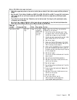
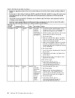
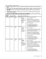
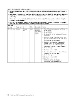
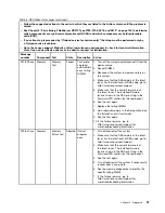
Table 3. DSA Preboot messages (continued)

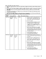
• Follow the suggested actions in the order in which they are listed in the Action column until the problem is

solved.

• See Chapter 9 “Parts listing, ThinkServer RD210 Type 3795, 3796, 3818, and 3819” on page 143 to determine

which components are customer replaceable units (CRU) and which components are field replaceable
units (FRU).

• If an action step is preceded by “(Trained service technician only),” that step must be performed only by

a Trained service technician.

• Go to the Lenovo support Web site at http://www.lenovo.com/support to check for technical information,

hints, tips, and new device drivers or to submit a request for information.

Message
number

Component Test

State

Description

Action

405-902-xxx

BroadCom
Ethernet
Device

Test
EEPROM

Failed

1. Make sure that the component firmware is

at the latest level. The installed firmware
level is shown in the DSA event log in the
Firmware/VPD section for this component.

2. Run the test again.

3. Replace the component that is causing the

error. If the error is caused by an adapter,
replace the adapter. Check the PCI Information
and Network Settings information in the DSA
event log to determine the physical location of
the failing component.

4. If the failure remains, go to

http://www.lenovo.com/support for
more troubleshooting information.

405-903-xxx

BroadCom
Ethernet
Device

Test
Internal
Memory

Failed

1. Make sure that the component firmware is

at the latest level. The installed firmware
level is shown in the DSA event log in the
Firmware/VPD section for this component.

2. Run the test again.

3. Check the interrupt assignments in the PCI

Hardware section of the DSA event log. If
the Ethernet device is sharing interrupts,
if possible, use the Setup utility (see the

Installation and User Guide

) to assign a unique

interrupt to the device.

4. Replace the component that is causing the

error. If the error is caused by an adapter,
replace the adapter. Check the PCI Information
and Network Settings information in the DSA
event log to determine the physical location of
the failing component.

5. If the failure remains, go to

http://www.lenovo.com/support for
more troubleshooting information.

58

ThinkServer RD210 Hardware Maintenance Manual

Summary of Contents for ThinkServer RD210

Page 1: ...ThinkServer RD210 Hardware Maintenance Manual ThinkServer RD210 Types 3795 3796 3818 and 3819 ...

Page 2: ......

Page 3: ...ThinkServer RD210 Hardware Maintenance Manual ThinkServer RD210 Types 3795 3796 3818 and 3819 ...

Page 4: ...a computer software and services have been developed exclusively at private expense and are sold to governmental entities as commercial items as defined by 48 C F R 2 101 with limited and restricted rights to use reproduction and disclosure LIMITED AND RESTRICTED RIGHTS NOTICE If products data computer software or services are delivered pursuant a General Services Administration GSA contract use r...

Page 5: ... 72 Removing the cover 72 Replacing the cover 73 Internal cable routing and connectors 73 Removing and installing the microprocessor 2 air baffle 76 Removing the microprocessor 2 air baffle 76 Installing the microprocessor 2 air baffle 76 Removing and installing the DIMM air baffle 77 Removing the DIMM air baffle 77 Installing the DIMM air baffle 77 Removing and installing a hot swap hard disk dri...

Page 6: ...lling a remotely installed RAID adapter battery 124 Removing a remotely installed RAID adapter battery 124 Installing a RAID adapter remotely in the server 126 Removing and installing the bezel 127 Removing the bezel 127 Installing the bezel 128 Removing and installing the operator information panel assembly 129 Removing the operator information panel assembly 129 Installing the operator informati...

Page 7: ...Korean Class A warning statement 172 Copyright Lenovo 2005 2010 vii ...

Page 8: ...viii ThinkServer RD210 Hardware Maintenance Manual ...

Page 9: ... ATTENZIONE e PERICOLO presenti nel manuale prima di eseguire una qualsiasi delle istruzioni Certifique se de ler todas as instruções de cuidado e perigo neste manual antes de executar qualquer uma das instruções Es importante que lea todas las declaraciones de precaución y de peligro de este manual antes de seguir las instrucciones Important information about replacing RoHS compliant FRUs RoHS Th...

Page 10: ...er June 2006 Current or original part Replacement FRU Current or original part Replacement FRU Non RoHS Can be Non RoHS Non RoHS Can be RoHS Non RoHS Can sub to RoHS RoHS Must be RoHS Must be RoHS Must be RoHS Note A direct substitution is a part with a different FRU part number that is automatically shipped by the distribution center at the time of order Turkish statement of compliance The Lenovo...

Page 11: ...product installeert eerst de veiligheidsvoorschriften Ennen kuin asennat tämän tuotteen lue turvaohjeet kohdasta Safety Information Avant d installer ce produit lisez les consignes de sécurité Vor der Installation dieses Produkts die Sicherheitshinweise lesen Prima di installare questo prodotto leggere le Informazioni sulla Sicurezza Les sikkerhetsinformasjonen Safety Information før du installere...

Page 12: ... face or a bulging capacitor Mechanical hazards such as loose or missing hardware To inspect the product for potential unsafe conditions complete the following steps 1 Make sure that the power is off and the power cord is disconnected 2 Make sure that the exterior cover is not damaged loose or broken and observe any sharp edges 3 Check the power cord Make sure that the third wire ground connector ...

Page 13: ...ns Make sure that another person who is familiar with the power off controls is near you and is available to turn off the power if necessary When you are working with powered on electrical equipment use only one hand Keep the other hand in your pocket or behind your back to avoid creating a complete circuit that could cause an electrical shock When you use a tester set the controls correctly and u...

Page 14: ...installing moving or opening covers on this product or attached devices To Connect To Disconnect 1 Turn everything OFF 2 First attach all cables to devices 3 Attach signal cables to connectors 4 Attach power cords to outlet 5 Turn device ON 1 Turn everything OFF 2 First remove power cords from outlet 3 Remove signal cables from connectors 4 Remove all cables from devices Statement 2 CAUTION When r...

Page 15: ...to the beam do not view directly with optical instruments and avoid direct exposure to the beam Class 1 Laser Product Laser Klasse 1 Laser Klass 1 Luokan 1 Laserlaite Appareil A Laser de Classe 1 Statement 4 18 kg 39 7 lb 32 kg 70 5 lb 55 kg 121 2 lb CAUTION Use safe practices when lifting Statement 5 CAUTION The power control button on the device and the power switch on the power supply do not tu...

Page 16: ...ith one of these parts contact a service technician Statement 26 CAUTION Do not place any object on top of rack mounted devices Attention This server is suitable for use on an IT power distribution system whose maximum phase to phase voltage is 240 V under any distribution fault condition Important This product is not suitable for use with visual display workplace devices according to Clause 2 of ...

Page 17: ...features with legacy BIOS compatibility UEFI compliant servers are capable of booting UEFI compliant operating systems BIOS based operating systems and BIOS based adapters as well as UEFI compliant adapters Note This server does not support DOS Dual core or quad core processingThe server supports up to two Xeon dual core or quad core microprocessors The server comes with only one microprocessor in...

Page 18: ...s failover capability to a redundant Ethernet connection with the applicable application installed If a problem occurs with the primary Ethernet connection and the optional Ethernet daughter card is installed on the server all Ethernet traffic that is associated with the primary connection is automatically switched to the optional redundant Ethernet daughter card connection If the applicable devic...

Page 19: ...e information is collected into a file that you can send to service and support Additionally you can view the information locally through a generated text report file You can also copy the log to a removable media and view the log from a Web browser For additional information about diagnostics see the Hardware Maintenance Manual EasyStartup DVDThe ThinkServer EasyStartup program guides you through...

Page 20: ...ems management network This system management connector is dedicated to the IMM functions This connector is active with or without IMM Premium One serial port RAID controllers A ServeRAID BR10i SAS SATA Controller that provides RAID levels 0 1 and 1E comes standard on some hot swap SAS and hot swap SATA models An optional ServeRAID MR10i SAS SATA Controller that provides RAID levels 0 1 1E 5 6 and...

Page 21: ...e DVD and can be accessed directly from the program s interface EasyManage The ThinkServer EasyManage Core server provides centralized hardware and software inventory management and secure automated system management through a centralized console The ThinkServer EasyManage Agent enables other clients on the network to be managed by the centralized console The ThinkServer EasyManage Core Server is ...

Page 22: ...14 ThinkServer RD210 Hardware Maintenance Manual ...

Page 23: ...s Software or operating system error codes See the documentation for the software or operating system for information about a specific error code See the manufacturer s Web site for documentation Light path diagnostics LEDs See the Installation and User Guide for information about LEDs that are lit b Collect system data Run Dynamic System Analysis DSA Preboot diagnostics program to collect informa...

Page 24: ... is available for download on Go to http www lenovo com thinkserver click the Options tab 2 Make sure that the server operating system and software are installed and configured correctly Many configuration problems are caused by loose power or signal cables or incorrectly seated adapters You might be able to solve the problem by turning off the server reconnecting cables reseating adapters and tur...

Page 25: ...r product number machine type and model number or select Servers and Storage from the Select your product list 3 From Family list select ThinkServer and click Continue 4 Click on Troubleshooting For more troubleshooting information see the Installation and User Guide If the problem remains contact Lenovo or an approved warranty service provider for assistance with additional problem determination ...

Page 26: ...18 ThinkServer RD210 Hardware Maintenance Manual ...

Page 27: ...er and all attached devices Step 2 Turn on all attached devices then turn on the server Step 3 When the prompt F2 Diagnostics is displayed press F2 Note The DSA Preboot diagnostic program might appear to be unresponsive for an unusual length of time when you start the program This is normal operation while the program loads Step 4 Optionally select Quit to DSA to exit from the stand alone memory d...

Page 28: ...LEDs are lit to indicate an error they remain lit when the server is turned off provided that the server is still connected to power and the power supply is operating correctly Before working inside the server to view EasyLED LEDs read the safety information in Chapter 2 Safety information on page 3 and Installation guidelines on page 67 If an error occurs view the EasyLED LEDs in the following or...

Page 29: ...rror but indicate that you will not take immediate action The system error LED flashes while it is in Remind mode and stays in Remind mode until one of the following conditions occurs All known errors are corrected The server is restarted A new error occurs causing the system error LED to be lit again EasyLED switch The EasyLED switch allows you to review error indications after the server has bee...

Page 30: ...ard disk drive backplane 3 Restart the server to see if the problem remains 4 Reinstall each device that was removed in step b one at a time starting the server each time to isolate the failing device 5 Replace any failing device 6 Trained service technician only Replace the system board if the problem remains If the 12V channel B error LED is lit complete the following steps 1 Turn the server off...

Page 31: ...hat was removed in step b one at a time starting the server each time to isolate the failing device 5 Replace any failing device 6 Trained service technician only Replace the system board if the problem remains If the 12V channel D error LED is lit complete the following steps 1 Turn the server off and disconnect the power from the server 2 Remove the microprocessor in socket 1 Note The server wil...

Page 32: ...ime to isolate the failing device 5 Replace any failing device 6 Trained service technician only Replace the system board if the problem remains LOG An error occurred Check the IMM system event log and the system error log for information about the error Replace any components identified in the error logs LINK Reserved PS Power supply 1 or 2 has failed 1 Make sure that the power supplies are seate...

Page 33: ...d 1 Check the microprocessors that were just installed to make sure that they are compatible with each other 2 Trained service technician only Replace the incompatible microprocessor 3 Check the system error logs for information about the error Replace any components identified in the error log CPU A microprocessor has failed 1 Make sure that the failing microprocessor which is indicated by a lit ...

Page 34: ...ips and new device drivers or to submit a request for information Message number Component Test State Description Action 089 801 xxx CPU CPU Stress Test Aborted Internal program error 1 Turn off and restart the system 2 Make sure that the DSA code is at the latest level For the latest level of DSA code go to http www lenovo com support 3 Run the test again 4 Make sure that the system firmware is a...

Page 35: ...t level For the latest level of DSA code go to http www lenovo com support 3 Run the test again 4 Make sure that the system firmware is at the latest level The installed firmware level is shown in the DSA event log in the Firmware VPD section for this component For the latest level of firmware go to http www lenovo com support 5 Run the test again 6 Turn off and restart the system if necessary to ...

Page 36: ... CPU CPU Stress Test Failed Test failure 1 Turn off and restart the system if necessary to recover from a hung state 2 Make sure that the DSA code is at the latest level For the latest level of DSA code go to http www lenovo com support 3 Run the test again 4 Make sure that the system firmware is at the latest level The installed firmware level is shown in the DSA event log in the Firmware VPD sec...

Page 37: ...e and turn on the system 3 Run the test again 4 Make sure that the DSA code is at the latest level For the latest level of DSA code go to http www lenovo com support 5 Make sure that the IMM firmware is at the latest level The installed firmware level is shown in the DSA event log in the Firmware VPD section for this component 6 Run the test again 7 If the failure remains go to http www lenovo com...

Page 38: ... turn on the system 3 Run the test again 4 Make sure that the DSA code is at the latest level For the latest level of DSA code go to http www lenovo com support 5 Make sure that the IMM firmware is at the latest level The installed firmware level is shown in the DSA event log in the Firmware VPD section for this component 6 Run the test again 7 If the failure remains go to http www lenovo com supp...

Page 39: ...ce and turn on the system 3 Run the test again 4 Make sure that the DSA code is at the latest level For the latest level of DSA code go to http www lenovo com support 5 Make sure that the IMM firmware is at the latest level The installed firmware level is shown in the DSA event log in the Firmware VPD section for this component 6 Run the test again 7 If the failure remains go to http www lenovo co...

Page 40: ...Run the test again 4 Make sure that the DSA code is at the latest level For the latest level of DSA code go to http www lenovo com support 5 Make sure that the IMM firmware is at the latest level The installed firmware level is shown in the DSA event log in the Firmware VPD section for this component 6 Run the test again 7 If the failure remains go to http www lenovo com support for more troublesh...

Page 41: ...e and turn on the system 3 Run the test again 4 Make sure that the DSA code is at the latest level For the latest level of DSA code go to http www lenovo com support 5 Make sure that the IMM firmware is at the latest level The installed firmware level is shown in the DSA event log in the Firmware VPD section for this component 6 Run the test again 7 If the failure remains go to http www lenovo com...

Page 42: ...d turn on the system 3 Run the test again 4 Make sure that the DSA code is at the latest level For the latest level of DSA code go to http www lenovo com support 5 Make sure that the IMM firmware is at the latest level The installed firmware level is shown in the DSA event log in the Firmware VPD section for this component 6 Run the test again 7 If the failure remains go to http www lenovo com sup...

Page 43: ...urce and turn on the system 3 Run the test again 4 Make sure that the DSA code is at the latest level For the latest level of DSA code go to http www lenovo com support 5 Make sure that the IMM firmware is at the latest level The installed firmware level is shown in the DSA event log in the Firmware VPD section for this component 6 Run the test again 7 If the failure remains go to http www lenovo ...

Page 44: ...3 Run the test again 4 Make sure that the DSA code is at the latest level For the latest level of DSA code go to http www lenovo com support 5 Make sure that the IMM firmware is at the latest level The installed firmware level is shown in the DSA event log in the Firmware VPD section for this component 6 Run the test again 7 If the failure remains go to http www lenovo com support for more trouble...

Page 45: ...source and turn on the system 3 Run the test again 4 Make sure that the DSA code is at the latest level For the latest level of DSA code go to http www lenovo com support 5 Make sure that the IMM firmware is at the latest level The installed firmware level is shown in the DSA event log in the Firmware VPD section for this component 6 Run the test again 7 If the failure remains go to http www lenov...

Page 46: ...on the system 3 Run the test again 4 Make sure that the DSA code is at the latest level For the latest level of DSA code go to http www lenovo com support 5 Make sure that the IMM firmware is at the latest level The installed firmware level is shown in the DSA event log in the Firmware VPD section for this component 6 Run the test again 7 If the failure remains go to http www lenovo com support fo...

Page 47: ...ystem to the power source and turn on the system 3 Run the test again 4 Make sure that the DSA code is at the latest level For the latest level of DSA code go to http www lenovo com support 5 Make sure that the IMM firmware is at the latest level The installed firmware level is shown in the DSA event log in the Firmware VPD section for this component 6 Run the test again 7 If the failure remains g...

Page 48: ...ource and turn on the system 3 Run the test again 4 Make sure that the DSA code is at the latest level For the latest level of DSA code go to http www lenovo com support 5 Make sure that the IMM firmware is at the latest level The installed firmware level is shown in the DSA event log in the Firmware VPD section for this component 6 Run the test again 7 If the failure remains go to http www lenovo...

Page 49: ... Action 166 901 xxx IMM IMM I2C Test Failed The IMM indicates a failure in the H8 bus Bus 0 1 Turn off the system and disconnect it from the power source You must disconnect the system from ac power to reset the IMM 2 After 45 seconds reconnect the system to the power source and turn on the system 3 Run the test again 4 Make sure that the DSA code is at the latest level For the latest level of DSA...

Page 50: ...onnect the system from ac power to reset the IMM 2 After 45 seconds reconnect the system to the power source and turn on the system 3 Run the test again 4 Make sure that the DSA code is at the latest level For the latest level of DSA code go to http www lenovo com support 5 Make sure that the IMM firmware is at the latest level The installed firmware level is shown in the DSA event log in the Firm...

Page 51: ...fter 45 seconds reconnect the system to the power source and turn on the system 3 Run the test again 4 Make sure that the DSA code is at the latest level For the latest level of DSA code go to http www lenovo com support 5 Make sure that the IMM firmware is at the latest level The installed firmware level is shown in the DSA event log in the Firmware VPD section for this component 6 Run the test a...

Page 52: ... failure in the power supply bus Bus 3 1 Turn off the system and disconnect it from the power source You must disconnect the system from ac power to reset the IMM 2 After 45 seconds reconnect the system to the power source and turn on the system 3 Run the test again 4 Make sure that the DSA code is at the latest level For the latest level of DSA code go to http www lenovo com support 5 Make sure t...

Page 53: ...t installed 1 Turn off the system and disconnect it from the power source You must disconnect the system from ac power to reset the IMM 2 After 45 seconds reconnect the system to the power source and turn on the system 3 Run the test again 4 Make sure that the DSA code is at the latest level For the latest level of DSA code go to http www lenovo com support 5 Make sure that the IMM firmware is at ...

Page 54: ...the power source and turn on the system 3 Run the test again 4 Make sure that the DSA code is at the latest level For the latest level of DSA code go to http www lenovo com support 5 Make sure that the IMM firmware is at the latest level The installed firmware level is shown in the DSA event log in the Firmware VPD section for this component 6 Run the test again 7 Turn off the system and disconnec...

Page 55: ...hat the server firmware is at the latest level The installed firmware level is shown in the DSA event log in the Firmware VPD section for this component 5 Run the test again 6 If the failure remains go to http www lenovo com support for more troubleshooting information 201 803 xxx Memory Memory Test Aborted Test canceled could not enable the processor cache 1 Turn off and restart the system 2 Run ...

Page 56: ... installed firmware level is shown in the DSA event log in the Firmware VPD section for this component 4 Run the test again 5 If the failure remains go to http www lenovo com support for more troubleshooting information 201 806 xxx Memory Memory Test Aborted Test canceled the memory controller fast scrub operation was not completed 1 Turn off and restart the system 2 Run the test again 3 Make sure...

Page 57: ...he test again 5 If the failure remains go to http www lenovo com support for more troubleshooting information 201 809 xxx Memory Memory Test Aborted Test canceled program error operation running fast scrub 1 Turn off and restart the system 2 Run the test again 3 Make sure that the DSA code is at the latest level For the latest level of DSA code go to http www lenovo com support 4 Make sure that th...

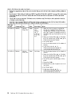
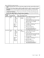
Page 58: ...number Component Test State Description Action 201 901 xxx Memory Memory Test Failed Test failure single bit error failing DIMM z 1 Turn off the system and disconnect it from the power source 2 Reseat DIMM z 3 Reconnect the system to power and turn on the system 4 Make sure that the DSA code is at the latest level For the latest level of DSA code go to http www lenovo com support 5 Make sure that ...

Page 59: ...e is at the latest level For the latest level of DSA code go to http www lenovo com support 5 Make sure that the server firmware is at the latest level The installed firmware level is shown in the DSA event log in the Firmware VPD section for this component 6 Run the test again 7 Replace the failing DIMMs 8 Re enable all memory in the Setup utility see the Installation and User Guide 9 Run the tes...

Page 60: ...sure that all memory is enabled by checking the Available System Memory in the Resource Utilization section of the DSA event log If necessary enable all memory in the Setup utility see the Installation and User Guide 2 Make sure that the DSA code is at the latest level For the latest level of DSA code go to http www lenovo com support 3 Run the test again 4 Run the standard memory test to validate...

Page 61: ...n Action 215 801 xxx Optical Drive Verify Media Installed Read Write Test Self Test Messages and actions apply to all three tests Aborted Unable to communicate with the device driver 1 Make sure that the DSA code is at the latest level For the latest level of DSA code go to http www lenovo com support 2 Run the test again 3 Check the drive cabling at both ends for loose or broken connections or da...

Page 62: ...nds 2 Run the test again 3 Insert a new CD DVD into the drive and wait for 15 seconds for the media to be recognized 4 Run the test again 5 Check the drive cabling at both ends for loose or broken connections or damage to the cable Replace the cable if it is damaged 6 Run the test again 7 Make sure that the DSA code is at the latest level For the latest level of DSA code go to http www lenovo com ...

Page 63: ... into the drive or try a new media and wait for 15 seconds 2 Run the test again 3 Check the drive cabling at both ends for loose or broken connections or damage to the cable Replace the cable if it is damaged 4 Run the test again 5 For additional troubleshooting information see the Installation and User Guide 6 Run the test again 7 Replace the CD DVD drive 8 If the failure remains go to http www l...

Page 64: ... the drive cabling at both ends for loose or broken connections or damage to the cable Replace the cable if it is damaged 4 Run the test again 5 Make sure that the DSA code is at the latest level For the latest level of DSA code go to http www lenovo com support 6 Run the test again 7 For additional troubleshooting information see the Installation and User Guide 8 Run the test again 9 Replace the ...

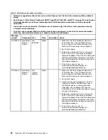
Page 65: ...ting information 405 901 xxx BroadCom Ethernet Device Test Control Registers Failed 1 Make sure that the component firmware is at the latest level The installed firmware level is shown in the DSA event log in the Firmware VPD section for this component 2 Run the test again 3 Replace the component that is causing the error If the error is caused by an adapter replace the adapter Check the PCI Infor...

Page 66: ...causing the error If the error is caused by an adapter replace the adapter Check the PCI Information and Network Settings information in the DSA event log to determine the physical location of the failing component 4 If the failure remains go to http www lenovo com support for more troubleshooting information 405 903 xxx BroadCom Ethernet Device Test Internal Memory Failed 1 Make sure that the com...

Page 67: ...vent log If the Ethernet device is sharing interrupts if possible use the Setup utility see the Installation and User Guide to assign a unique interrupt to the device 4 Replace the component that is causing the error If the error is caused by an adapter replace the adapter Check the PCI Information and Network Settings information in the DSA event log to determine the physical location of the fail...

Page 68: ... Network Settings information in the DSA event log to determine the physical location of the failing component 4 If the failure remains go to http www lenovo com support for more troubleshooting information 405 908 xxx BroadCom Ethernet Device Test LEDs Failed 1 Make sure that the component firmware is at the latest level The installed firmware level is shown in the DSA event log in the Firmware V...

Page 69: ... use the default configuration values and automatically goes to F1 Setup To solve the problem complete the following steps 1 Undo any configuration changes that you made recently and restart the server 2 Remove any devices that you added recently and restart the server 3 If the problem remains go to Setup and select Load Default Settings and then click Save to restore the server factory settings C...

Page 70: ...62 ThinkServer RD210 Hardware Maintenance Manual ...

Page 71: ... safety in mind The lithium battery must be handled correctly to avoid possible danger If you replace the battery you must adhere to the following instructions If you replace the original lithium battery with a heavy metal battery or a battery with heavy metal components be aware of the following environmental consideration Batteries and accumulators that contain heavy metals must not be disposed ...

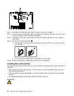
Page 72: ...d out of its housing b Use your thumb and index finger to lift the battery from the socket Step 5 Dispose of the battery as required by local ordinances or regulations Installing the system battery The following notes describe information that you must consider when replacing the system board battery in the server When replacing the system board battery you must replace it with a lithium battery o...

Page 73: ...tallation instructions that come with the replacement battery Step 2 Insert the new battery a Tilt the battery so that you can insert it into the socket on the side opposite the battery clip b Press the battery down into the socket until it clicks into place Make sure that the battery clip holds the battery securely Step 3 Install the cover see the Installation and User Guide for instructions Step...

Page 74: ...66 ThinkServer RD210 Hardware Maintenance Manual ...

Page 75: ...tem is installed or that a I9990305 error code is displayed indicating that an operating system was not found but the server is otherwise working correctly If the server is not working correctly see the Hardware Maintenance Manual for diagnostic information Observe good housekeeping in the area where you are working Place removed covers and other parts in a safe place If you must start the server ...

Page 76: ...ers You have replaced a failed fan within 48 hours You have replaced a hot swap drive within 2 minutes of removal Working inside the server with the power on Attention Static electricity that is released to internal server components when the server is powered on might cause the server to halt which might result in the loss of data To avoid this potential problem always use an electrostatic discha...

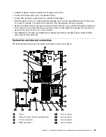
Page 77: ...ting down the device If it is necessary to set down the device put it back into its static protective package Do not place the device on the server cover or on a metal surface Take additional care when you handle devices during cold weather Heating reduces indoor humidity and increases static electricity System board internal connectors The following illustration shows the internal connectors on t...

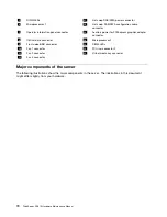
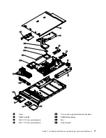
Page 78: ... Optical drive connector 20 Microprocessor 2 9 Front video USB connector 21 DIMM LEDs 10 Fan 1 connector 22 PCI riser connector 2 11 Fan 2 connector 23 Virtual media key connector 12 Fan 3 connector Major components of the server The following illustrations show the major components in the server The illustrations in this document might differ slightly from your hardware 70 ThinkServer RD210 Hardw...

Page 79: ...000 000000 000000 1 Cover 10 2 5 inch hot swap hard disk drive filler panel 2 DIMM air baffle 11 SAS SATA backplane 3 Slot 2 PCI riser card assembly 12 Fans 4 Slot 1 PCI riser card assembly 13 System board Chapter 7 Installing optional devices and replacing customer replaceable units 71 ...

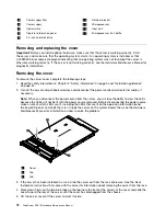
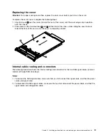
Page 80: ...r cords and all external cables if necessary Note When you disconnect the power source from the server you will lose the ability to view the LEDs because the LEDs will not be lit with the power source removed Before disconnecting the power source make a note of which LEDs are lit including the LEDs that are lit on the operation information panel the EasyLED panel and LEDs that are lit inside the s...

Page 81: ...cover is completely closed 000000 000000 000000 000000 000000 0 0 0 000000 000000 000000 000000 000000 Internal cable routing and connectors The following illustration shows the internal routing and connectors for the two SAS signal cables in server models with eight SAS drive bays Notes 1 To connect the SAS signal cables make sure that you first connect the signal cable and then the power cable a...

Page 82: ...er and signal cable with a shared connector on both ends The following illustration shows the internal routing and connector for the SATA cable 1 The following illustration shows the internal routing and connector for the operator information panel cable 74 ThinkServer RD210 Hardware Maintenance Manual ...

Page 83: ...for the USB video cable Note The USB cable is routed under the video cable and then both the USB and video cables are routed under the cable retention tab and the top cover latch receptacle Table 6 1 Top cover latch receptacle 2 Cable retention tab Chapter 7 Installing optional devices and replacing customer replaceable units 75 ...

Page 84: ...fore you turn on the server Operating the server with the air baffle removed might damage server components 000000 000000 000000 000000 000000 0 0 0 000000 000000 000000 000000 000000 Installing the microprocessor 2 air baffle To install the microprocessor 2 air baffle if you removed it complete the following steps 1 Read the safety information in Chapter 2 Safety information on page 3 and Install...

Page 85: ...nformation on how to solve the problem 3 Grasp the DIMM air baffle 2 and lift the baffle up making sure that the pin 1 comes out of the pin hole 3 on the system board to the left of DIMM connector 8 000000 000000 000000 000000 000000 0 0 0 000000 000000 000000 000000 000000 4 Remove it from the server and set it aside Installing the DIMM air baffle Attention For proper cooling and airflow replace ...

Page 86: ...or SATA ID for that device The server supports six 2 5 inch hot swap SAS or hot swap SATA hard disk drives All hot swap drives in the server should have the same throughput speed rating Mixing hard disk drives with different speed ratings will cause all drives to operate at the lower throughput speed Do not mix SAS and SATA hard disk drives in the same system The electromagnetic interference EMI i...

Page 87: ...ns in addition to the instructions in this chapter Make sure that you have all the cables and other equipment that are specified in the documentation that comes with the drive Select the bay in which you want to install the drive Check the instructions that come with the drive to determine whether you have to set any switches or jumpers on the drive If you are installing a SAS or SATA device be su...

Page 88: ...nuously that drive is faulty and must be replaced If the green hard disk drive activity LED is flashing the drive is being accessed Note If the server is configured for RAID operation using a RAID adapter you might have to reconfigure your disk arrays after you install hard disk drives See the RAID adapter documentation for additional information about RAID operation and complete instructions for ...

Page 89: ...ing the LEDs that are lit on the operation information panel the EasyLED panel and LEDs that are lit inside the server on the system board then see the Hardware Maintenance Manual for information on how to solve the problem 3 Remove the cover see Removing and replacing the cover on page 72 4 If an adapter is installed in the riser card assembly disconnect any cables that are connected to the adapt...

Page 90: ...system board 000000 000000 000000 000000 000000 0 0 0 000000 000000 000000 000000 000000 000 000 000 0000 0000 0000 1 PCI riser card assembly full height full length adapters 2 PCI riser card assembly low profile adapters 3 PCI riser connector 1 4 PCI riser connector 2 Removing and installing an adapter The following describe the types of adapters that the server supports and other information tha...

Page 91: ...itch the PCI adapter from slot 1 riser assembly to slot 2 you will need to remove the screw from the standard bracket and then replace the standard bracket with the low profile bracket The server provides two PCI riser card slots To install any PCI adapter both the AC and DC power cords must be disconnected from the power source before you remove the PCI Express riser assembly Otherwise this will ...

Page 92: ...tor This is the highest resolution that is supported for any add on video adapter that you install in the server 3 Any high definition video out connector or stereo connector on any add on video adapter is not supported 1 Read the safety information in Chapter 2 Safety information on page 3 and Installation guidelines on page 67 2 Turn off the server and peripheral devices and disconnect the power...

Page 93: ...ou have other options to install or remove do so now Otherwise go to Completing the installation on page 130 Removing and installing a memory module DIMMs To remove and install a memory module complete the steps in this section Removing a memory module DIMMs To remove a dual inline memory module DIMM complete the following steps 1 Read the safety information in Chapter 2 Safety information on page...

Page 94: ...The specifications of a DDR3 DIMM are on a label on the DIMM in the following format gggeRxff PC3 wwwwwm aa bb cc where ggg is the total capacity of the DIMM for example 1GB 2GB or 4GB e is the number of ranks 1 single rank 2 dual rank 4 quad rank ff is the device organization bit width 4 x4 organization 4 DQ lines per SDRAM 8 x8 organization 16 x16 organization wwwww is the DIMM bandwidth in MBps...

Page 95: ...install a minimum of two DIMMs if the server has two microprocessors installed However to improve system performance install a minimum of three DIMMs for each microprocessor The maximum operating speed of the server is determined by the slowest DIMM installed in the server The server comes with a minimum of two 1 GB DIMMs installed in connectors 3 and 6 When you install additional DIMMs install th...

Page 96: ...sts the DIMM connectors on each memory channel Table 10 Connectors on each memory channel Memory channel DIMM connectors Channel 0 1 2 3 9 10 11 Channel 1 4 5 6 12 13 14 Channel 2 7 8 15 16 The following illustration shows the memory connector layout that is associated with each microprocessor For example DIMM connectors 9 10 11 12 13 14 15 and 16 DIMM connectors are shown underneath the boxes are...

Page 97: ...air of DIMMs 2 12 9 Note DIMM connectors 7 8 15 and 16 are not used in memory mirroring mode When you install or remove DIMMs the server configuration information changes When you restart the server the system displays a message that indicates that the memory configuration has changed The following illustration shows the location of the DIMMs connectors on the system board Chapter 7 Installing opt...

Page 98: ...pen the retaining clips 2 on each end of the DIMM connector and remove the DIMM 1 Attention To avoid breaking the retaining clips or damaging the DIMM connectors open and close the clips gently 7 Touch the static protective package that contains the DIMM to any unpainted metal surface on the outside of the server Then remove the DIMM from the package 8 Turn the DIMM so that the DIMM keys align cor...

Page 99: ...th the power source removed Before disconnecting the power source make a note of which LEDs are lit including the LEDs that are lit on the operation information panel the EasyLED panel and LEDs that are lit inside the server on the system board then see EasyLED on page 20 for information on how to solve the problem 3 Remove the cover see Removing and replacing the cover on page 72 4 Disconnect the...

Page 100: ...ution verify that the latest level of code is supported for the cluster solution before you update the code 1 Read the safety information in Chapter 2 Safety information on page 3 and Installation guidelines on page 67 2 Turn off the server and peripheral devices and disconnect the power cords and all external cables if necessary Note When you disconnect the power source from the server you will l...

Page 101: ...roller 000000 000000 000000 000000 000000 0 0 0 7 Tilt the SAS SATA RAID riser card assembly slightly and insert the end of the adapter in the slot on the retention bracket as shown in the following illustration Make sure that the SAS SATA RAID riser card assembly keys align correctly with the connector on the system board and press down on the assembly until it is seated firmly into the connector...

Page 102: ...lustration show how to route the signal cables Note When you restart the server you will be prompted to import the existing RAID configuration to the new ServeRAID controller If you have other devices to install or remove do so now Otherwise go to Completing the installation on page 130 Removing and installing the optional IBM ServeRAID MR10i SAS SATA Controller To remove and install the optional ...

Page 103: ...oblem 3 Remove the cover see Removing and replacing the cover on page 72 4 Touch the static protective package that contains the new ServeRAID MR10i SAS SATA controller to any unpainted surface on the outside of the server then grasp the adapter by the top edge or upper corners of the controller and remove it from the package 5 Align the ServeRAID MR10i SAS SATA controller so that the keys align c...

Page 104: ...n on the assembly until it is seated firmly into the connector on the system board 1 SAS SATA RAID front retention bracket 2 SAS SATA RAID riser card 3 ServeRAID MR10i adapter 4 Plastic tab 5 Alignment post 8 Route the signal cables from the drive backplane over the blue adapter retention bracket as shown in the following illustration 0 0 00 00 00 00 1 Connector for drive bays 0 3 signal cable 2 C...

Page 105: ...o the existing SAS SATA controller from the connectors on the controller 5 Grasp the SAS SATA controller near the end next to the power supply cage and press the black plastic tab next to the power supply that is holding the controller in place toward the power supply 6 Pull up on the SAS SATA controller until the RAID riser card assembly disengages from the connector on the system board 7 Grasp t...

Page 106: ... serviceable parts inside these components If you suspect a problem with one of these parts contact a service technician Removing a hot swap power supply To remove a hot swap power supply complete the following steps 1 Read the safety information in Chapter 2 Safety information on page 3 and Installation guidelines on page 67 2 If only one power supply is installed turn off the server and peripher...

Page 107: ...on page 3 and Installation guidelines on page 67 2 Touch the static protective package that contains the hot swap power supply 2 to any unpainted metal surface on the server then remove the power supply 2 from the package and place it on a static protective surface 3 If you are installing a hot swap power supply into an empty bay remove the power supply filler panel 3 from the power supply bay 00 ...

Page 108: ...d fan within 30 seconds To remove a hot swap fan complete the following steps 1 Read the safety information in Chapter 2 Safety information on page 3 and Installation guidelines on page 67 2 Remove the cover see Removing and replacing the cover on page 72 The LED near the connector of the failing fan assembly is lit 3 Disconnect the cable of the failing fan from the connector 1 Fan tabs 6 Fan 4 2 ...

Page 109: ...Chapter 2 Safety information on page 3 and Installation guidelines on page 67 2 Remove the cover see Removing and replacing the cover on page 72 3 Touch the static protective package that contains the new fan to any unpainted metal surface on the server Then remove the new fan from the package 4 If you are replacing a fan grasp the orange fan tabs 1 on both ends of the existing fan and pull it up ...

Page 110: ...w Otherwise go to Completing the installation on page 130 Removing and installing the SAS SATA RAID riser card assembly To remove and install the SAS SATA RAID riser card assembly complete the steps in this section Removing the SAS SATA RAID riser card assembly To remove the SAS SATA RAID riser card assembly complete the following steps 1 Read the safety information in Chapter 2 Safety information...

Page 111: ...and peripheral devices and disconnect the power cords and all external cables then remove the server cover see Removing and replacing the cover on page 72 3 Reinstall the SAS SATA adapter if one was removed 4 Reinstall the flash device if it was removed 5 Align the SAS SATA RAID riser card assembly keys correctly with the connector on the system board and press down on the assembly until it is sea...

Page 112: ...rmation in Chapter 2 Safety information on page 3 and Installation guidelines on page 67 2 Turn off the server and peripheral devices and disconnect all power cords then remove the cover see Removing and replacing the cover on page 72 3 If necessary lift the riser card assembly out of the way see Removing and installing a PCI riser card assembly on page 81 4 Locate the battery on the system board ...

Page 113: ...ype battery recommended by the manufacturer If your system has a module containing a lithium battery replace it only with the same module type made by the same manufacturer The battery contains lithium and can explode if not properly used handled or disposed of Do not Throw or immerse into water Heat to more than 100 C 212 F Repair or disassemble Dispose of the battery as required by local ordinan...

Page 114: ...d disconnect the power cords and all external cables Note When you disconnect the power source from the server you will lose the ability to view the LEDs because the LEDs will not be lit with the power source removed Before disconnecting the power source make a note of which LEDs are lit including the LEDs that are lit on the operation information panel the EasyLED panel and LEDs that are lit insi...

Page 115: ...w PCI riser card assembly see Removing and installing a PCI riser card assembly on page 81 5 Set any jumpers or switches on the adapter as directed by the adapter manufacturer 6 Align the PCI riser card assembly with the PCI slot connector on the system board then press down firmly until the riser card assembly in seated correctly in the connector on the system board 000000 000000 000000 000000 00...

Page 116: ...from the slots 8 Push backwards on the backplane until it is clear of the slots 9 Lift the backplane out of the server 10 Disconnect the power cable and the signal cable from the disk drive backplane 1 Backplane tabs 2 Hard disk drive backplane 3 Backplane tabs 4 Backplane bracket slots 11 If you are instructed to return the backplane follow all packaging instructions and use any packaging materia...

Page 117: ...ripheral devices and the server Removing and installing the operator information panel assembly To remove and install the operator information panel assembly complete the steps in this section Removing the operator information panel assembly To remove the operator information panel complete the following steps 1 Read the safety information in Chapter 2 Safety information on page 3 and Installation...

Page 118: ...el complete the following steps 1 Read the safety information in Chapter 2 Safety information on page 3 and Installation guidelines on page 67 2 From the front of the server slide the operator information panel 1 into the server until it clicks into place 3 Inside the server connect the cable to the rear of the operator information panel assembly The following illustration shows the cable routing ...

Page 119: ... the server with the latest firmware or restore the pre existing firmware that the customer provides on a diskette or CD image Make sure that you have the latest firmware or a copy of the pre existing firmware before you proceed 1 Read the safety information in Chapter 2 Safety information on page 3 and Installation guidelines on page 67 2 Turn off the server and peripheral devices and disconnect ...

Page 120: ...u can later reinstall it in the same connector 8 Remove IMM Premium from the system board and set it aside You will have to install IMM Premium on the new system board 9 Disconnect all cables from the system board Make a list of each cable as you disconnect it you can then use this as a checklist when you install the new system board 10 Remove the hot swap fans see Removing and installing a hot sw...

Page 121: ... the chassis 000000 000000 000000 000000 000000 0 0 0 000000 000000 000000 000000 000000 3 Grasp the fan assembly brackets and rotate them down toward the chassis 4 Reinstall the hot swap fans see Removing and installing a hot swap fan assembly on page 100 5 Reinstall the microprocessor and heat sink 6 Reinstall the SAS SATA RAID riser card assembly base see Removing and installing the SAS SATA RA...

Page 122: ...ing a CD DVD drive To remove and install a CD DVD drive complete the steps in this section Removing a CD DVD drive To remove a CD DVD drive complete the following steps 1 Read the safety information in Chapter 2 Safety information on page 3 and Installation guidelines on page 67 2 Turn off the server and peripheral devices and disconnect all power cords 3 Remove the cover see Removing and replacin...

Page 123: ... that are specified in the documentation that comes with the drive The server supports one ultra slim SATA optical drive The server comes standard with a CD DVD ROM installed If you need to replace a CD DVD drive complete the following steps 1 Read the safety information in Chapter 2 Safety information on page 3 and Installation guidelines on page 67 2 Turn off the server and peripheral devices an...

Page 124: ... ROMs DVD drives fiber optic devices or transmitters are installed note the following Do not remove the covers Removing the covers of the laser product could result in exposure to hazardous laser radiation There are no serviceable parts inside the device Use of controls or adjustments or performance of procedures other than those specified herein might result in hazardous radiation exposure 116 Th...

Page 125: ...e system board The following illustration shows the cable routing for the CD DVD drive Note The CD DVD cable should go on the top of the operation information panel cable in the middle and the Video USB cable on the bottom when all three cables are installed in the server 13 Reconnect the power cord and any cables that you removed 14 Turn on the peripheral devices and the server Removing a CD DVD ...

Page 126: ...page 67 2 Turn off the server and peripheral devices and disconnect all power cords and external cables 3 Align the cable connector with the connector on the rear of the optical drive cage and press the cable connector into the optical drive cage connector until it is firmly seated 4 Pull the cable connector latch up and hold it there while you slide the cable connector to the left then slide the ...

Page 127: ... peripheral devices and the server Removing and installing the virtual media key To remove and install the virtual media key complete the steps in this section Removing the virtual media key To remove the virtual media key complete the following steps 1 Read the safety information in Chapter 2 Safety information on page 3 and Installation guidelines on page 67 2 Turn off the server and peripheral ...

Page 128: ...all the virtual media key complete the following steps 1 Read the safety information in Chapter 2 Safety information on page 3 and Installation guidelines on page 67 2 Remove the cover see Removing and replacing the cover on page 72 3 Align the virtual media key with the mounting tab and slide it down the tab onto the connector on the system board Press the virtual media key down into the connecto...

Page 129: ... port Ethernet adapter complete the following steps 1 Read the safety information in Chapter 2 Safety information on page 3 and Installation guidelines on page 67 2 Turn off the server and peripheral devices and disconnect all power cords 3 Remove the cover see Removing and replacing the cover on page 72 4 Remove the PCI riser card assembly from PCI riser connector 1 see Removing and installing a ...

Page 130: ... see Removing and replacing the cover on page 72 3 Touch the static protective package that contains the Ethernet adapter to any unpainted metal surface on the server Then remove the Ethernet adapter from the package 4 Remove the Ethernet adapter filler panel on the rear of the chassis if it has not been removed already 5 Attach the Ethernet adapter bracket to the Ethernet adapter if the bracket i...

Page 131: ...plete the following steps 1 Read the safety information in Chapter 2 Safety information on page 3 and Installation guidelines on page 67 2 Turn off the server and peripheral devices and disconnect all power cords 3 Remove the cover see Removing and replacing the cover on page 72 4 Remove the PCI riser card assembly from PCI riser connector 1 see Removing and installing a PCI riser card assembly on...

Page 132: ...Reconnect the power cords and any cables that you removed 11 Turn on the peripheral devices and the server Removing and installing a remotely installed RAID adapter battery To remove and install a remotely installed RAID adapter battery complete the steps in this section Removing a remotely installed RAID adapter battery If a RAID adapter battery is installed remotely on the microprocessor 2 air b...

Page 133: ...2 Remote battery cable connector 3 Battery 4 Battery carrier 5 Battery connector 6 Disconnect the battery cable from the battery cable connector on the battery carrier 7 Remove the three screws that attaches the battery carrier to the battery and remove the battery from the battery carrier Note If your battery 1 and battery carrier 2 are attached with a clip squeeze the clip on the side of the bat...

Page 134: ... devices and disconnect all power cords 3 Remove the cover see Removing and replacing the cover on page 72 4 Route the remote battery cable through the notches on the microprocessor 2 air baffle Attention Make sure that the cable is not pinched and does not cover any connectors or obstruct any components on the system board 5 Install the battery on the microprocessor 2 air baffle Connect the batte...

Page 135: ... cables and turn on the server and peripheral devices Removing and installing the bezel To remove and install the bezel complete the steps in this section Removing the bezel To remove the bezel complete the following steps 1 Read the safety information in Chapter 2 Safety information on page 3 and Installation guidelines on page 67 2 Turn off the server and peripheral devices and disconnect all po...

Page 136: ...f the bezel into the holes on the chassis 2 Rotate the bezel 2 upward to the server and reinstall the bezel screws 1 3 Reinstall the screws on the video connector 3 4 Reinstall the hard disk drives and drive bay filler panels into the drive bays 5 Install the cover see Removing and replacing the cover on page 72 6 Reconnect the power cords and any cables that you removed 7 Slide the server into th...

Page 137: ...the blue push point on the rear of the panel to the front of the server 6 From the front of the server carefully pull the assembly out of the server while you move it slightly from side to side 7 If you are instructed to return the operator information panel assembly follow all packaging instructions and use any packaging materials for shipping that are supplied to you Installing the operator info...

Page 138: ... installed in the server 1 Operator information panel cable 2 Operator information panel connector 4 Install the cover see Removing and replacing the cover on page 72 5 Slide the server into the rack 6 Reconnect the power cords and any cables that you removed 7 Turn on the peripheral devices and the server Completing the installation To complete the installation complete the following steps 130 Th...

Page 139: ...activity LED green 11 Rack release latch 2 Hard disk drive status LED amber 12 USB 2 connector 3 Drive bay 0 13 Optical drive eject button 4 Drive bay 2 14 Optical drive activity LED 5 Drive bay 4 15 Optical drive bay 6 Power control button and LED 16 Drive bay 5 7 Operator information panel 17 Drive bay 3 8 Operator information panel release latch 18 Drive bay 1 9 Video connector 19 Rack release ...

Page 140: ...e with the server and optional devices Use these identifiers to connect the cables to the correct connectors 1 USB cable release lever 2 USB cable There are release levers on the Ethernet and systems management connectors To disconnect a cable from one of these connectors pull up on the lever to release the cable 1 Ethernet activity LED 3 Ethernet speed LED 2 Ethernet port 4 Ethernet cable release...

Page 141: ... has an optional RAID adapter and you have installed or removed a hard disk drive see the documentation that comes with the RAID adapter for information about reconfiguring the disk arrays For information about configuring the integrated Gigabit Ethernet controller see the User Guide Chapter 7 Installing optional devices and replacing customer replaceable units 133 ...

Page 142: ...134 ThinkServer RD210 Hardware Maintenance Manual ...

Page 143: ... Guide for instructions 4 Remove the screw 3 from the safety cover 2 5 Disconnect the hard disk drive backplane cables from the connector on the front of the safety cover 2 6 Slide the safety cover 2 forward to disengage it from the system board then lift it out of the server 7 If you are instructed to return the safety cover 2 follow all packaging instructions and use any packaging materials for ...

Page 144: ...microprocessor socket Do not touch the microprocessor contacts handle the microprocessor by the edges only Contaminants on the microprocessor contacts such as oil from your skin can cause connection failures between the contacts and the socket To remove a microprocessor and heat sink complete the following steps Step 1 Read the safety information see Chapter 2 Safety information on page 3 Step 2 T...

Page 145: ... other information that you must consider when you install a microprocessor and heat sink The server supports up to two Intel Xeon dual core or quad core microprocessors See http www lenovo com thinkserverfor a list of supported microprocessors Do not mix dual core and quad core microprocessors in the same server The upgrade of microprocessors are not supported on this server For example if the se...

Page 146: ...do not have to set any microprocessor frequency selection jumpers or switches If the thermal grease protective cover for example a plastic cap or tape liner is removed from the heat sink do not touch the thermal grease on the bottom of the heat sink or set down the heat sink For more information about applying or working with thermal grease see Thermal grease on page 140 Note Removing the heat sin...

Page 147: ...then carefully place the microprocessor on the socket and close the microprocessor bracket frame 1 Note The microprocessor fits only one way on the socket e Carefully close the microprocessor release lever 4 to the closed position to secure the microprocessor in the socket 3 Install the heat sink a Clean the grease from the heat sink and apply new grease on the microprocessor b Align the heat sink...

Page 148: ...steps 1 Place the heat sink on a clean work surface 2 Remove the cleaning pad from its package and unfold it completely 3 Use the cleaning pad to wipe the thermal grease from the bottom of the heat sink Note Make sure that all of the thermal grease is removed 4 Use a clean area of the cleaning pad to wipe the thermal grease 1 from the microprocessor 2 then dispose of the cleaning pad after all of ...

Page 149: ...n lift the retention module from the system board Step 7 If you are instructed to return the heat sink retention module follow all the packaging instructions and use any packaging materials for shipping that are supplied to you Installing a heat sink retention module To install a heat sink retention module complete the following steps Step 1 Read the safety information see Chapter 2 Safety informa...

Page 150: ...Step 8 Reconnect the power cords and any cables that you removed Step 9 Turn on the peripheral devices and the server 142 ThinkServer RD210 Hardware Maintenance Manual ...

Page 151: ...ervice CRUs these CRUs unplug or are secured by no more than two screws Examples of these types of CRUs include a USB device or the power cord Other Self service CRUs depending on product design might include hot swap hard disk drives hot swap fans hot swap power supplies memory DIMMs and RAID cards Optional service CRUs these CRUs are isolated parts within the server and are concealed by an acces...

Page 152: ... 00 0000 0000 0000 000000 000000 000000 000000 000000 00 00 000000 000000 000000 000000 The following table lists the part numbers for the server components 144 ThinkServer RD210 Hardware Maintenance Manual ...

Page 153: ...44T1492 5 Memory IBM 4 GB dual rank 2Rx4 PC3 10600R 999 DDR3 Chipkill RDIMM 1333 MHz models CTO 44T1493 6 Virtual media key models CTO All Models 42D0545 7 Power supply bay filler models CTO All Models 49Y4821 8 Power supply 675 Watt models CTO 21U 21S 21Y 21G 21M 21V 21E 39Y7201 9 Chassis assembly without front bezel models N A 10 SATA DVD ROM models CTO 44W3254 10 SATA Mulit burn models CTO 21U ...

Page 154: ...croprocessor Quad Core Intel Xeon E5540 2 53GHz 8MB L2 Cache 1066MHz FSB 80w models CTO 46D1265 23 Microprocessor Quad Core Intel Xeon E5530 2 4GHz 8MB L2 Cache 1066MHz FSB 80w models CTO 46D1266 23 Microprocessor Quad Core Intel Xeon E5520 2 26GHz 8MB L2 Cache 1066MHz FSB 80w models CTO 46D1267 23 Microprocessor Quad Core Intel Xeon L5520 2 26GHz 8MB L2 Cache 1066MHz FSB LV 60w models CTO 46D1269...

Page 155: ...Alcohol wipes models CTO All Models 59P4739 Diagnostics Panel models CTO All Models 46U2140 HBA SAS Adapter models CTO all Models 42D0516 Integrated Management Module IMM Premium HW Key models CTO all Models 46C7528 LSI MR10M SAS SATA controller models CTO 43W4341 MR 10is SAS SATA controller models CTO all Models 44E8696 BR 10i SAS Controller models CTO all Models 44E8690 Benelli SIT models CTO al...

Page 156: ...1333 MHz models CTO 44T1492 5 Memory IBM 4 GB dual rank 2Rx4 PC3 10600R 999 DDR3 Chipkill RDIMM 1333 MHz models CTO 44T1493 6 Virtual media key models CTO All Models 42D0545 7 Power supply bay filler models CTO All Models 49Y4821 8 Power supply 675 Watt models CTO All Models 39Y7201 9 Chassis assembly without front bezel N A 10 SATA CD RW DVD models CTO 44W3255 10 SATA DVD ROM models CTO 44W3254 1...

Page 157: ... models CTO 46D1268 23 Microprocessor Quad Core Intel Xeon X5570 2 93GHz 8MB L2 Cache 1333MHz FSB 95w models CTO 46D1262 23 Microprocessor Quad Core Intel Xeon X5550 2 67GHz 8MB L2 Cache 1333MHz FSB 95w models CTO 46D1264 23 Microprocessor Quad Core Intel Xeon E5540 2 53GHz 8MB L2 Cache 1066MHz FSB 80w models CTO 24G 24M 24V 24E 2CU 2CS 2CY 2CG 2CM 2CV 2CE 2DG 2DM 2DR 2DE 46D1265 23 Microprocessor...

Page 158: ...dels CTO All Models 43V6938 Slide rail kit models CTO All Model 49Y4816 Thermal grease kit models CTO All Model 41Y9292 Alcohol wipes models CTO All Model 59P4739 Bling Bling Ops Diag Panel models CTO All Model 46M3560 Diagnostics Panel models CTO All Model 46U2140 Staked chassis models CTO All Model 49Y4813 EIA Brackets models CTO All Model 49Y4815 HBA SAS Adapter models CTO All Model 42D0516 Int...

Page 159: ... 5 Memory 2GB DDR3 1333 2Rx8 LP RDIMM models CTO 46U1992 5 Memory 2GB DDR3 1333 1Rx4 LP RDIMM models CTO 46U1993 5 Memory 4GB DDR3 1333 2Rx4 LP RDIMM models CTO 46U1994 5 Memory IBM 1 GB single rank 1Rx8 PC3 10600R 999 DDR3 Chipkill RDIMM 1333 MHz models CTO 44T1490 5 Memory IBM 2 GB dual rank 2Rx8 PC3 10600R 999 DDR3 Chipkill RDIMM 1333 MHz models CTO 44T1491 5 Memory IBM 2 GB single rank 1Rx4 PC...

Page 160: ...nk models CTO All Models 49Y4822 23 Microprocessor Quad Core Intel Xeon X5560 2 8GHz 8MB L2 Cache 1333MHz FSB 95w models CTO 46D1263 23 Microprocessor Quad Core Intel Xeon L5506 2 13GHz 4MB L2 Cache 800MHz FSB LV 60w models CTO 46D1268 23 Microprocessor Quad Core Intel Xeon X5570 2 93GHz 8MB L2 Cache 1333MHz FSB 95w models CTO 46D1262 23 Microprocessor Quad Core Intel Xeon X5550 2 67GHz 8MB L2 Cac...

Page 161: ...ofile adapter models Miscellaneous parts kit models CTO All Models 49Y4814 Riser card bracket full height half length models Riser card bracket low profile models CTO All Models 43V6939 Bracket assembly rear I O models CTO All Models 43V6938 SAS adapter retainer models ServeRAID MR10i battery carrier kit models Slide rail kit models CTO All Models 49Y4816 Thermal grease kit models CTO All Models 4...

Page 162: ...er Tier 2 FRU part number 1 Top cover models CTO All Models 43V6933 2 DIMM air duct models CTO All Models 43V6931 3 PCI X riser card assembly models CTO All Models 43V6936 4 PCI Express riser card x16 assembly models N A 5 Memory 1GB DDR3 1333 1Rx8 LP RDIMM models CTO 26U 26S 26Y 26G 26M 26E 46U1991 5 Memory 2GB DDR3 1333 2Rx8 LP RDIMM models CTO 46U1992 5 Memory 2GB DDR3 1333 1Rx4 LP RDIMM models...

Page 163: ...models 46U2760 15 Filler hot swap hard disk drive models N A 16 Backplane SAS hard disk drive models CTO 46C4148 17 Fan hot swap 40 mm models CTO 43V6929 18 System board models CTO 26U 26S 26Y 26G 26M 26E 43V7072 19 ServeRAID MR10i adapter models CTO 43W4297 20 ServeRAID BR10i adapter models 43W4297 22 Retention module heat sink models CTO All Models 49Y4822 23 Microprocessor Quad Core Intel Xeon ...

Page 164: ...CTO All Models 43V7019 Cable SAS signal 200 mm models CTO All Models 43V6922 Cable USB video models CTO All Models 43V6920 Cover safety 240VA models CTO All Models 49Y4823 EMC filler models CTO 44T2248 Ethernet card models CTO 43V7073 Labels system service models CTO All Models 49Y4812 Miscellaneous parts kit models CTO All Models 49Y4814 Riser card bracket low profile models CTO All Models 43V693...

Page 165: ...roller models CTO 46M0922 M5000 advance raid feature key models CTO 46M0931 ServeRAID M5015 SAS SATA controller models CTO all Models 46M0851 NetXtreme II 1000 Express Ethernet adapter models CTO all Models 39Y6070 The following consumable parts are available for purchase from the retail store Table 16 Consumable parts Types 3795 Index Description Part number Battery 3 0 volt ServeRAID MR10i batte...

Page 166: ...of a minimum 18 AWG Type SVT or SJT three conductor cord a maximum of 15 feet in length and a tandem blade grounding type attachment plug rated 15 amperes 250 volts For units intended to be operated at 230 volts outside the U S Use a cord set with a grounding type attachment plug The cord set should have the appropriate safety approvals for the country in which the equipment will be installed Powe...

Page 167: ... All Models 69Y9967 ENT64 HK CTO All Models 69Y9968 ENT64 RU CTO All Models 46U2898 SBS Prem English CTO All Models 46U2899 SBS Prem French CTO All Models 46U2900 SBS Prem German CTO All Models 46U2901 SBS Prem Japanese CTO All Models 46U2902 SBS Prem Spanish CTO All Models 46U2903 EBS STD English CTO All Models 46U2904 EBS Premium English CTO All Models Table 21 Power Cords Types 3796 Power cord ...

Page 168: ...e virtual media key CTO All Models 69Y9937 Easy manage DVD CTO All Models 69Y9938 Documentation CTO All Models 69Y9939 Easy start up DVD CTO All Models 69Y9952 SBS64US CTO All Models 69Y9953 EBS64US CTO All Models 69Y9954 STD64CT CTO All Models 69Y9955 STD64HK CTO All Models 69Y9956 STD64RU CTO All Models 69Y9957 ENT64US CTO All Models 69Y9958 ENT64FR CTO All Models 69Y9959 ENT64GR CTO All Models ...

Page 169: ...models CTO 39M5158 Switzerland 2 8M models CTO 25S 25G 39M5172 Israel 2 8M models CTO 25G 39M5179 Europe 2 8M models CTO 39M5219 Korea 2 8M models CTO 39M5226 India 2 8M models CTO 39M5233 Brazil 2 8M models CTO 39M5247 Taiwan 2 8M models CTO Software FRUs Used in these countries and regions 46U3203 Flash drive virtual media key CTO All Models 69Y9937 Easy manage DVD CTO All Models 69Y9938 Documen...

Page 170: ...es 3819 Power cord part number Used in these countries and regions 39M5068 Argentina 2 8M models CTO 26Y 39M5081 US Canada 2 8M models CTO 26U 26S 26V 39M5199 Japan 2 8M models CTO 26E 39M5123 Europe 2 8M models CTO 39M5165 Italy 2 8M models CTO 26Y 26G 39M5102 ANZ 2 8M models CTO 26M 39M5130 Denmark 2 8M models CTO 26G 39M5144 S Africa 2 8M models CTO 26G 26M 39M5151 UK 2 8M models CTO 39M5158 Sw...

Page 171: ...9Y9961 ENT64 IT CTO All Models 69Y9962 ENT64 SP CTO All Models 69Y9963 ENT64 TR CTO All Models 69Y9964 ENT64 NL CTO All Models 69Y9965 ENT64 KR CTO All Models 69Y9966 ENT64 CT CTO All Models 69Y9967 ENT64 HK CTO All Models 69Y9968 ENT64 RU CTO All Models 46U2898 SBS Prem English CTO All Models 46U2899 SBS Prem French CTO All Models 46U2900 SBS Prem German CTO All Models 46U2901 SBS Prem Japanese C...

Page 172: ...164 ThinkServer RD210 Hardware Maintenance Manual ...

Page 173: ...ublication Lenovo may make improvements and or changes in the product s and or the program s described in this publication at any time without notice The products described in this document are not intended for use in implantation or other life support applications where malfunction may result in injury or death to persons The information contained in this document does not affect or change Lenovo...

Page 174: ...he United States other countries or both Other company product or service names may be trademarks or service marks of others Important notes Processor speed indicates the internal clock speed of the microprocessor other factors also affect application performance CD or DVD drive speed is the variable read rate Actual speeds vary and are often less than the possible maximum When referring to proces...

Page 175: ...only to countries within the European Union EU and Norway This appliance is labeled in accordance with European Directive 2002 96 EC concerning waste electrical and electronic equipment WEEE The Directive determines the framework for the return and recycling of used appliances as applicable throughout the European Union This label is applied to various products to indicate that the product is not ...

Page 176: ...nne pour le retour et le recyclage des batteries et accumulateurs usés Cette étiquette est appliquée sur diverses batteries pour indiquer que la batterie ne doit pas être mise au rebut mais plutôt récupérée en fin de cycle de vie selon cette norme In accordance with the European Directive 2006 66 EC batteries and accumulators are labeled to indicate that they are to be collected separately and rec...

Page 177: ...ance statement This Class A digital apparatus complies with Canadian ICES 003 Avis de conformité à la réglementation d Industrie Canada Cet appareil numérique de la classe A est conforme à la norme NMB 003 du Canada Australia and New Zealand Class A statement Attention This is a Class A product In a domestic environment this product may cause radio interference in which case the user may be requir...

Page 178: ...sche Verträglichkeit von Betriebsmitteln EMVG vom 20 Juli 2007 früher Gesetz über die elektromagnetische Verträglichkeit von Geräten bzw der EMV EG Richtlinie 2004 108 EC früher 89 336 EWG für Geräte der Klasse A Dieses Gerät ist berechtigt in Übereinstimmung mit dem Deutschen EMVG das EG Konformitätszeichen CE zu führen Verantwortlich für die Konformitätserklärung nach Paragraf 5 des EMVG ist die...

Page 179: ...Japanese Voluntary Control Council for Interference VCCI statement Japanese recycling statements Appendix A Notices 171 ...

Page 180: ...Taiwanese Class A warning statement Chinese Class A warning statement Korean Class A warning statement 172 ThinkServer RD210 Hardware Maintenance Manual ...

Page 181: ......

Page 182: ...Part Number 40M2493 Printed in USA 1P P N 40M2493 40M2493 ...

Reviews: