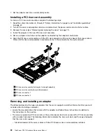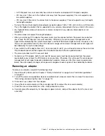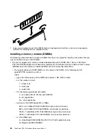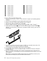
– Channel 2, DIMM connectors 8 ,7, 15, and 16 are not used in memory-mirroring mode.
– The maximum available memory is reduced to half of the installed memory when memory mirroring
is enabled. For example, if you install 64 GB of memory, only 32 GB of addressable memory is
available when you use memory mirroring.
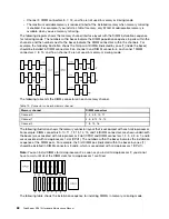
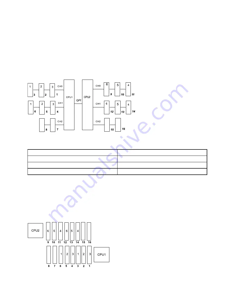
The following diagram shows the memory channel interface layout with the DIMM installation sequence
for mirroring mode. The numbers within boxes indicate the DIMM population sequence in pairs within the
channels, and the numbers next to the boxes indicate the DIMM connectors within the channels. For
example, the following illustration shows the first pair of DIMMs (indicated by ones (1) inside the boxes)
should be installed in DIMM connectors 3 on channel 0 and DIMM connector 6 on channel 1 DIMM
connectors 7, 8, 15, and 16 on channel 2 are not used in memory-mirroring mode.
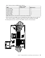
The following table lists the DIMM connectors on each memory channel.
Table 10. Connectors on each memory channel
Memory channel
DIMM connectors
Channel 0
1, 2, 3, 9, 10, 11
Channel 1
4, 5, 6, 12, 13, 14
Channel 2
7, 8, 15, 16
The following illustration shows the memory connector layout that is associated with each microprocessor.
For example, DIMM connectors 9, 10, 11, 12, 13, 14, 15, and 16 (DIMM connectors are shown underneath
the boxes) are associated with microprocessor 2 slot (CPU2) and DIMM connectors 1, 2, 3, 4, 5, 6, 7, and 8
are associated with microprocessor 1 slot (CPU1). The numbers within the boxes indicates the installation
sequence of the DIMM pairs. For example, the first DIMM pair (indicated within the boxes by ones (1)
should be installed in DIMM connectors 3 and 6, which is associated with microprocessor 1 (CPU1).
Note:
You can install DIMMs for microprocessor 2 as soon as you install microprocessor 2; you do not
have to wait until all of the DIMM slots for microprocessor 1 are filled.
The following table shows the installation sequence for installing DIMMs in memory-mirroring mode:
88
ThinkServer RD210 Hardware Maintenance Manual
Summary of Contents for ThinkServer RD210
Page 1: ...ThinkServer RD210 Hardware Maintenance Manual ThinkServer RD210 Types 3795 3796 3818 and 3819 ...
Page 2: ......
Page 3: ...ThinkServer RD210 Hardware Maintenance Manual ThinkServer RD210 Types 3795 3796 3818 and 3819 ...
Page 7: ...Korean Class A warning statement 172 Copyright Lenovo 2005 2010 vii ...
Page 8: ...viii ThinkServer RD210 Hardware Maintenance Manual ...
Page 22: ...14 ThinkServer RD210 Hardware Maintenance Manual ...
Page 26: ...18 ThinkServer RD210 Hardware Maintenance Manual ...
Page 70: ...62 ThinkServer RD210 Hardware Maintenance Manual ...
Page 74: ...66 ThinkServer RD210 Hardware Maintenance Manual ...
Page 142: ...134 ThinkServer RD210 Hardware Maintenance Manual ...
Page 172: ...164 ThinkServer RD210 Hardware Maintenance Manual ...
Page 181: ......
Page 182: ...Part Number 40M2493 Printed in USA 1P P N 40M2493 40M2493 ...

