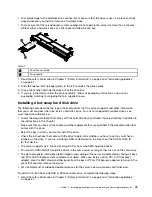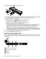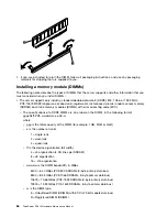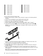
11. Reconnect the power cord and any cables that you removed.
12. Replace the cover (see “Removing and replacing the cover” on page 72).
13. Turn on the peripheral devices and the server.
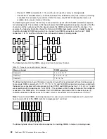
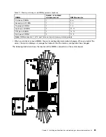
DIMM installation sequence
Memory mirroring
Installation steps
Removing and installing the IBM ServeRAID-BR10i SAS/SATA Controller
To remove and install the IBM ServeRAID-BR10i SAS/SATA Controller, complete the steps in this section.
Removing the IBM ServeRAID-BR10i SAS/SATA Controller
To remove the IBM ServeRAID-BR10i SAS/SATA controller from the system board, complete the following
steps:
1. Read the safety information in Chapter 2 “Safety information” on page 3 and “Installation guidelines”
on page 67.
2. Turn off the server and peripheral devices and disconnect the power cords.
Note:
When you disconnect the power source from the server, you will lose the ability to view the LEDs
because the LEDs will not be lit with the power source removed. Before disconnecting the power source,
make a note of which LEDs are lit, including the LEDs that are lit on the operation information panel, the
EasyLED panel, and LEDs that are lit inside the server on the system board; then, see “EasyLED” on
page 20 for information on how to solve the problem.
3. Remove the cover (see “Removing and replacing the cover” on page 72).
4. Disconnect the signal cables that are attached to the drive backplane from the connectors on the
controller.
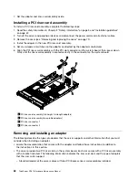
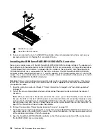
5. Grasp the SAS/SATA controller near the end next to the power-supply cage and press the black plastic
tab (next to the power supply) that is holding the controller in place toward the power supply.
6. Pull up on the SAS/SATA controller until the RAID riser card assembly disengages from the connector
on the system board.
1
USB embedded connector
2
RAID controller connector
3
Riser card error LED
4
SAS/SATA RAID riser card
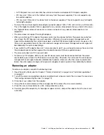
7. Grasp the SAS/SATA controller and pull it out of the connector on the RAID riser card assembly.
Chapter 7
.
Installing optional devices and replacing customer replaceable units
91
Summary of Contents for ThinkServer RD210
Page 1: ...ThinkServer RD210 Hardware Maintenance Manual ThinkServer RD210 Types 3795 3796 3818 and 3819 ...
Page 2: ......
Page 3: ...ThinkServer RD210 Hardware Maintenance Manual ThinkServer RD210 Types 3795 3796 3818 and 3819 ...
Page 7: ...Korean Class A warning statement 172 Copyright Lenovo 2005 2010 vii ...
Page 8: ...viii ThinkServer RD210 Hardware Maintenance Manual ...
Page 22: ...14 ThinkServer RD210 Hardware Maintenance Manual ...
Page 26: ...18 ThinkServer RD210 Hardware Maintenance Manual ...
Page 70: ...62 ThinkServer RD210 Hardware Maintenance Manual ...
Page 74: ...66 ThinkServer RD210 Hardware Maintenance Manual ...
Page 142: ...134 ThinkServer RD210 Hardware Maintenance Manual ...
Page 172: ...164 ThinkServer RD210 Hardware Maintenance Manual ...
Page 181: ......
Page 182: ...Part Number 40M2493 Printed in USA 1P P N 40M2493 40M2493 ...


