background image

1. Remove all external media from the drives and turn off all attached devices and the server. Then,

disconnect all power cords from electrical outlets and disconnect all cables that are connected to
the server.

2. Prepare your server. See “Removing or extending the server from the rack cabinet” on page 65.

3. Remove the server cover. See “Removing the server cover” on page 65.

4. Remove the riser card assembly and lay it upside down on a flat, clean, and static-protective surface.

See “Replacing the riser card” on page 81.

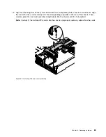
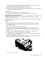
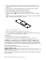
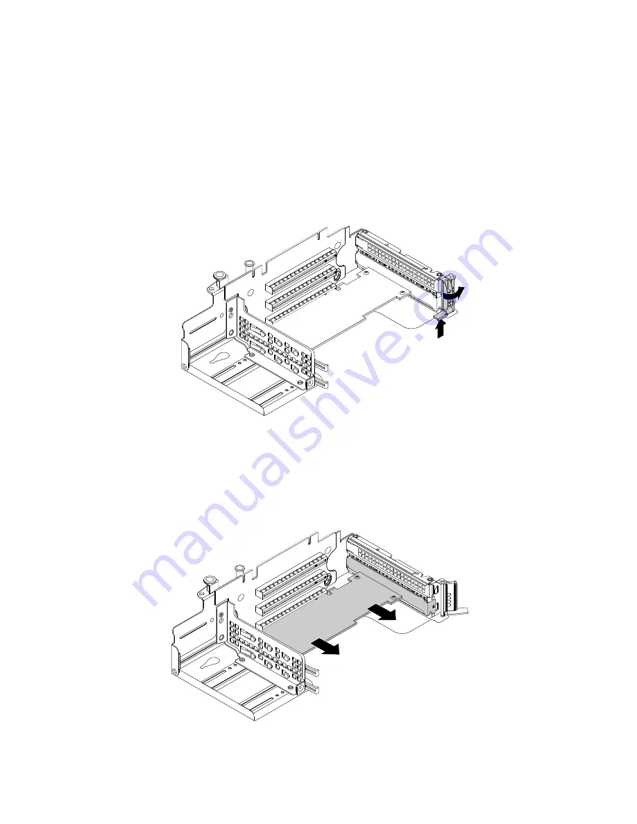
5. Locate the PCIe card you want to remove. Then, press the tab to pivot the card latch to the open

position.

Figure 64. Pivoting the card latch to the open position

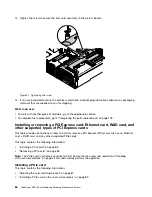
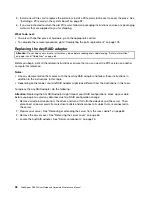
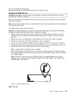
6. Grasp the PCIe card by its edges and carefully pull it out of the PCIe slot.

Note:

The PCIe card might fit tightly into the PCIe slot. If necessary, alternatively move each side of the

PCIe card a small and equal amount until it is removed from the slot.

Figure 65. Removing the PCIe card

96

ThinkServer RD450 User Guide and Hardware Maintenance Manual

Summary of Contents for ThinkServer RD450

Page 1: ...ThinkServer RD450 User Guide and Hardware Maintenance Manual Machine Types 70DA 70DB 70DC 70DD 70DE 70DF 70DV 70DW 70Q9 70QA 70QQ 70QR 70QS 70QT 70QV and 70QW ...

Page 2: ... product Safety information on page iii Appendix A Notices on page 193 Fifth Edition March 2016 Copyright Lenovo 2014 2016 LIMITED AND RESTRICTED RIGHTS NOTICE If data or software is delivered pursuant to a General Services Administration GSA contract use reproduction or disclosure is subject to restrictions set forth in Contract No GS 35F 05925 ...

Page 3: ...ver 49 Turning off the server 49 Chapter 5 Configuring the server 51 Using the Setup Utility program 51 Starting the Setup Utility program 51 Viewing information in the Setup Utility program 51 Setup Utility program interface 51 Setting the system date and time 54 Using passwords 54 Selecting a startup device 55 Configuring the TPM function 56 Setting an Ethernet connector for system management 56...

Page 4: ...cement 178 Reinstalling the server cover and reconnecting cables 178 Updating the server configuration 181 Chapter 7 Troubleshooting and diagnostics 183 Troubleshooting procedure 183 Viewing the status and diagnostic LEDs 183 Viewing the system event log 184 Basic troubleshooting tables 184 Lenovo ThinkServer Deployment Manager program problems 184 Optical drive problems 184 Storage drive problems...

Page 5: ...n käyttöä Avant d utiliser le produit veillez à bien lire et comprendre les instructions de sécurité multilingues figurant sur le DVD de documentation fourni avec le produit Πριν χρησιμοποιήσετε το προϊόν βεβαιωθείτε ότι έχετε διαβάσει και κατανοήσει τις οδηγίες ασφάλειας οι οποίες είναι διαθέσιμες σε διάφορες γλώσσες στο DVD τεκμηρίωσης που συνοδεύει το προϊόν Vor Verwendung des Produkts sollten ...

Page 6: ... s produktom Preden začnete uporabljati izdelek je pomembno da preberete in razumete večjezična varnostna navodila na DVD ju z dokumentacijo ki ste ga prejeli skupaj z izdelkom Antes de utilizar el producto asegúrese de leer y comprender las instrucciones de seguridad multilingües del DVD de documentación que se proporciona con el producto Var noga med att läsa säkerhetsinstruktionerna på dokument...

Page 7: ... instructed otherwise in the installation and configuration procedures Connect and disconnect cables as described in the following table when installing moving or opening covers on this product or attached devices To connect To disconnect 1 Turn everything OFF 2 First attach all cables to devices 3 Attach signal cables to connectors 4 Attach power cords to outlets 5 Turn devices ON 1 Turn everythi...

Page 8: ...ss 3B laser diode Note the following Laser radiation when open Do not stare into the beam do not view directly with optical instruments and avoid direct exposure to the beam Statement 4 18 kg 39 7 lb 32 kg 70 5 lb 55 kg 121 2 lb 32 kg 70 5 lb 55 kg 121 2 lb 100 kg 220 5 lb CAUTION Use safe practices when lifting Statement 5 CAUTION The power control button on the device and the power switch on the...

Page 9: ...s will not support the weight of the device Statement 8 CAUTION Never remove the cover on a power supply or any part that has the following label attached Hazardous voltage current and energy levels are present inside any component that has this label attached There are no serviceable parts inside these components If you suspect a problem with one of these parts contact a service technician Statem...

Page 10: ...ded on the rails Statement 14 CAUTION Some accessory or option board outputs exceed Class 2 or limited power source limits You must install the appropriate interconnecting cabling in accordance with your local electrical code requirements Statement 15 CAUTION The power control button on the device may put the device in standby mode instead of turning off the device In addition the device might hav...

Page 11: ...nts Use 1 3 mm2 or 16 American Wire Gauge AWG copper conductor only not exceeding 3 meters in length Torque the wiring terminal screws to 1 4 newton meters or 12 inch pounds Provide a readily available approved and rated disconnect device in the field wiring Statement 17 CAUTION This product contains a Class 1M laser Do not view directly with optical instruments Statement 18 CAUTION Do not place a...

Page 12: ...her you can continue without first correcting the problem Consider these conditions and the safety hazards they present Electrical hazards especially primary power primary voltage on the frame can cause serious or fatal electrical shock Explosive hazards such as a damaged Cathode Ray Tube CRT monitor or a bulging capacitor Mechanical hazards such as loose or missing hardware To determine whether t...

Page 13: ...worn frayed or pinched cables 9 Check that the power supply cover fasteners screws or rivets have not been removed or tampered with Grounding requirements Electrical grounding of the server is required for operator safety and correct system function Proper grounding of the electrical outlet can be verified by a certified electrician Copyright Lenovo 2014 2016 xi ...

Page 14: ...xii ThinkServer RD450 User Guide and Hardware Maintenance Manual ...

Page 15: ...ntation DVD that comes with your server A printable generic version of the latest LLW also is available in more than 30 languages at http www lenovo com warranty llw_02 If you cannot obtain the LLW through the documentation DVD or Lenovo Web site contact your local Lenovo office or reseller to obtain a printed version of the LLW free of charge For warranty service consult the worldwide Lenovo Supp...

Page 16: ...tion some locations offer extended privileges and services to registered users Server documentation This topic provides a general description of each document for your server and instructions on how to obtain all the documents Printed documents The following documents are printed out and included in your server package Read Me First This is a multilingual document you should read first This docume...

Page 17: ...t This document also includes the Lenovo warranty statement Customer Replaceable Units CRUs information and information about how to contact the Lenovo Customer Support Center Lenovo License Agreement This document includes the terms and conditions of the Lenovo License Agreement User Guide and Hardware Maintenance Manual This document provides detailed information to help you get familiar with yo...

Page 18: ...4 ThinkServer RD450 User Guide and Hardware Maintenance Manual ...

Page 19: ...Instructions that comes with the server 4 Connect the Ethernet cables and power cords to the server See Rear view of the server on page 23 to locate the connectors 5 Turn on the server to verify operation See Turning on the server on page 49 6 Review the Basic Input Output System BIOS settings and customize as needed See Using the Setup Utility program on page 51 7 Configure RAID and install the o...

Page 20: ...6 ThinkServer RD450 User Guide and Hardware Maintenance Manual ...

Page 21: ...tation and a documentation DVD Features This topic provides general information about the server features for a variety of models Depending on your specific model some features might vary or unavailable For information about your specific model use the Setup Utility program See Viewing information in the Setup Utility program on page 51 You also can refer to the Product Specifications Reference do...

Page 22: ...system fan fails To locate the system fans see System board components on page 41 If your server is installed with one microprocessor three system fans fan 1 to fan 3 are adequate to provide proper cooling However you must keep the location for fan 4 occupied by a dummy fan to ensure proper airflow If your server is installed with two microprocessors ensure that all the four system fans are instal...

Page 23: ... connectors To locate the connectors refer to the related topics in Locations on page 15 Video subsystem An integrated graphics controller is available in your server to support the VGA connectors for connecting video devices The integrated graphics controller is located in the Baseboard Management Controller BMC chip on the system board Integrated graphics controller On board ASPEED AST2400 16 MB...

Page 24: ... server With the TSM no matter what condition the server operating system is in and no matter if the server is on or off as long as the server is connected to network and an ac power source the interaction with the TSM controlled servers can be achieved through system network The user can obtain the server hardware health information and system event log SEL and is able to conduct the operations i...

Page 25: ...ke on LAN When the Wake on LAN feature is enabled on a server that is connected to a LAN a network administrator can remotely turn on or wake up the server from a management console using remote network management software Besides many other functions such as data transfer and software updates can be performed remotely without remote attendance and can be done after normal working hours and on wee...

Page 26: ...o 10 000 ft in an unpressurized environment Note When the altitude exceeds 950 m 3117 ft the defined maximum dry bulb temperature for operation becomes a dependent variable This temperature value decreases by 1 C 33 8 F with every 300 m 984 ft of altitude increase Humidity Operating 20 to 80 non condensing Storage without package 8 to 90 non condensing Storage with package 8 to 90 non condensing E...

Page 27: ...ed servers The system information includes component inventory component status and sensor status The program also enables users to perform management tasks such as restarting or turning off your ThinkServer server launching a remote console and accessing the TSM interface For detailed information about using the program refer to the help system of the program Lenovo Partner Pack for VMware vCente...

Page 28: ...evice driver bundle file for your server To find and download the bundle file go to http www lenovo com drivers and follow the instructions on the Web page 2 Launch Deployment Manager and click Platform Update on the left pane 3 Select Application and then click Next 4 Click Browse to select the corresponding bundle file and then click OK The version information is displayed 5 Click Flash to apply...

Page 29: ... helps to plan servers and devices deployment in an efficient way For detailed information about using the Lenovo ThinkServer Power Planner program refer to the help system of the program Lenovo ThinkServer System Manager The Lenovo ThinkServer System Manager TSM is a management solution that provides comprehensive and secure management features These features enable you to manage your servers rem...

Page 30: ... helps support technicians to identify your server and provide faster service The following illustrations are examples of the machine type model and serial number labels on server models with different drive bay configurations Note Depending on the model your server might look slightly different from the illustrations in this topic Figure 1 Label on server models with 3 5 inch drive bays 16 ThinkS...

Page 31: ...ew of server models with 2 5 inch drives and a slim optical drive on page 19 Front view of server models with an internal tape drive on page 20 Note Depending on the model your server might look slightly different from the illustrations in this topic Front view of server models with 3 5 inch drives 0 1 3 2 5 4 7 6 Figure 3 Front view of server models with 3 5 inch drives 1 Rack handle left 2 Front...

Page 32: ... 0 7 The EMI integrity and cooling of the server are protected by having all drive bays covered or occupied The number of the installed drives in your server varies by model The vacant drive bays are occupied by dummy trays When you install drives follow the order of the drive bay numbers Front view of server models with 2 5 inch drives 0 1 2 3 4 5 6 7 8 9 10 11 12 13 14 15 16 17 18 19 20 21 22 23...

Page 33: ...and a slim optical drive 0 1 2 3 4 5 6 7 8 9 10 11 12 13 14 15 Figure 5 Front view of server models with 2 5 inch drives and a slim optical drive 1 Rack handle left 2 Front panel 3 Pull out information card 4 2 5 inch drive bays 0 15 5 Slim optical drive available on some models 6 Rack handle right 1 6 Rack handles If your server is installed in a rack cabinet you can use the rack handles to help ...

Page 34: ...ilable on some models 6 Rack handle right 7 2 5 inch drive bays 0 7 1 6 Rack handles If your server is installed in a rack cabinet you can use the rack handles to help you slide the server out of the rack cabinet You also can use the rack handles and screws to secure the server in the rack cabinet so that the server cannot slide out especially in vibration prone areas For more information refer to...

Page 35: ...tration shows the controls connectors and LEDs on the front panel of the server To locate the front panel see Front view of the server on page 17 Figure 7 Front panel 1 Network status LED 2 System health LED 3 Power button with power status LED 4 System ID button with ID LED 5 USB 2 0 connectors 2 6 VGAconnector 1 Network status LED The network status LED on the front panel helps you identify the ...

Page 36: ...itical error Check the BMC for detailed information The power cord has been disconnected from one power supply or a redundant power supply has been removed 1 Ensure that the power supplies are installed securely in the server 2 Ensure that the power cords are connected securely to the power supplies 3 Install a new power supply to replace the removed one On Amber The server is overheated Check the...

Page 37: ... hub which you can use to connect additional USB devices 6 VGA connector Used to attach a VGA compatible video device such as a VGA monitor Rear view of the server This topic provides information to help you locate the connectors and components on the rear of your server Figure 8 Rear view of the server 1 Power supply 1 2 Power supply 2 available on some models 3 PCIe slot 6 4 PCIe slot 3 on riser...

Page 38: ...4 x2 x1 Low profile card 6 PCIe slot 5 x16 x8 x4 x2 x1 Low profile card 7 8 PCIe slots on riser card assembly 1 Slot Physical link width Negotiable link width Supported card length and height 7 PCIe slot 1 x16 x8 x4 x2 x1 Half length full height card 8 PCIe slot 2 x16 x8 x4 x2 x1 Half length full height card Note If your server is installed with only one microprocessor only PCIe slots 1 and 2 are ...

Page 39: ...On The connection speed is 1000 Mbps Green On The connection speed is 100 Mbps 1 Left data speed None Off The connection speed is 10 Mbps Green On The server is connected to a LAN None Off The server is disconnected from a LAN 2 Right link and activity Green Blinking The LAN is connected and active 13 Serial connector Used to attach a device that uses a 9 pin serial connector 15 VGA connector Used...

Page 40: ... inch drive area 5 Front VGA and USB module 6 Rack handle left 7 Front panel board 8 AnyRAID adapter available on some models 9 Hot swap drive backplane 10 System fan cage 11 System fan 12 System board 13 CPU1 DIMMs vary by model 14 Heat sink 15 Coin cell battery 16 Cooling shroud 17 ThinkServer RAID Super Capacitor Module available on some models 18 Riser card assembly 1 19 Riser card assembly 2 ...

Page 41: ...go to http www lenovo com serviceparts lookup Notes Before servicing a Lenovo product ensure that you read and understand Safety information on page iii Use only parts provided by Lenovo Available on some models FRU description Self service CRU Optional service CRU AnyRAID adapter No Yes AnyRAID flash module No Yes Coin cell battery Yes No Cooling shroud Yes No Easy swap drive module No Yes Easy s...

Page 42: ...ion kit for AnyRAID adapter or RAID card is designed for different types of servers and might contain additional cables that are not required for your server You server also supports the Host Bus Adapter The Host Bus Adapter is used to connect your server to external storage devices such as a storage array Your server supports the following AnyRAID adapters and RAID cards AnyRAID adapters supporte...

Page 43: ...apter provides SATA software RAID function The following illustration shows the connectors on the adapter Figure 11 Lenovo ThinkServer RAID 110i AnyRAID Adapter 1 SATA 0 3 connector Used to connect to the SATA connector 0 ports 0 3 on the system board See System board components on page 41 2 SATA 4 7 connector Used to connect to the SATA connector 1 ports 4 7 on the system board See System board c...

Page 44: ...ows the connectors on the adapter Figure 12 Lenovo ThinkServer RAID 510i AnyRAID Adapter 1 PCIE 0 connector 2 PCIE 1 connector Used to connect to the AnyRAID connector 0 1 on the system board See System board components on page 41 3 RAID upgrade key connector Used to connect a ThinkServer RAID 510i upgrade key 30 ThinkServer RD450 User Guide and Hardware Maintenance Manual ...

Page 45: ... adapter Figure 13 ThinkServer RAID 720i AnyRAID Adapter 1 ThinkServer RAID Super Capacitor Module connector available on some models Used to connect to the ThinkServer RAID Super Capacitor Module See Server components on page 25 2 PCIE 0 connector 3 PCIE 1 connector Used to connect to the AnyRAID connector 0 1 on the system board See System board components on page 41 Chapter 3 Product overview 3...

Page 46: ...Server RAID 720ix AnyRAID Adapter 1 SATA connector Used to connect the SATA signal cable from the internal tape drive if one is installed 2 ThinkServer RAID Super Capacitor Module connector Used to connect to the ThinkServer RAID Super Capacitor Module See Server components on page 25 3 PCIE 0 connector 4 PCIE 1 connector Used to connect to the AnyRAID connector 0 1 on the system board See System ...

Page 47: ...ector 0 Used to connect to the SAS connector 1 ports 0 3 on the backplane for up to eight 3 5 inch drives See Backplane for up to eight 3 5 inch drives on page 37 2 Connector 1 Used to connect to the SAS connector 2 ports 4 7 on the backplane for up to eight 3 5 inch drives See Backplane for up to eight 3 5 inch drives on page 37 3 RAID 500 upgrade key connector Used to connect a Lenovo ThinkServe...

Page 48: ...e 16 ThinkServer RAID 520i PCIe Adapter 1 Connector 0 Used to connect the mini SAS signal cable connector on the backplane to support HDD 0 3 2 Connector 1 Used to connect the mini SAS signal cable connector on the backplane to support HDD 4 7 3 J3 connector Used to connect to a ThinkServer RAID 520i upgrade key 34 ThinkServer RD450 User Guide and Hardware Maintenance Manual ...

Page 49: ... Used to connect to the SAS connector 1 ports 0 3 on the backplane for up to eight 3 5 inch drives See Backplane for up to eight 3 5 inch drives on page 37 2 Connector 2 Used to connect to the SAS connector 2 ports 4 7 on the backplane for up to eight 3 5 inch drives See Backplane for up to eight 3 5 inch drives on page 37 3 ThinkServer RAID Super Capacitor Module connector Used to connect the cab...

Page 50: ...lash Module connector Used to connect a Thunderbolt Memory module hereinafter referred to as TMM Hot swap drive backplane Your server comes with one of the following drive bay and backplane configurations Drive bay size Drive bay quantity Backplane quantity Drive type 3 5 inch 8 1 Hot swap SATA or SAS 3 5 inch hard disk drive or 2 5 inch solid state drive 2 5 inch 8 1 Hot swap SATA or SAS Hard dis...

Page 51: ... 10 pin backplane power connector on the system board to provide power to the backplane 9 SAS connector 2 ports 4 7 Used to connect to one of the following connectors SATA connector 1 ports 4 7 on the system board Port 1 on the Lenovo ThinkServer RAID 500 PCIe Adapter Port 2 on the Lenovo ThinkServer RAID 710 PCIe Adapter 10 2 pin power connector Used to connect to an optical drive if one is insta...

Page 52: ...ne for up to sixteen 2 5 inch drives 16 17 Figure 22 Rear view of the backplane for up to sixteen 2 5 inch drives 0 15 Slot 0 slot 15 Used to connect 2 5 inch drives 16 10 pin power connector 0 Used to connect to the 10 pin backplane power connector on the system board to provide power to the backplane 17 AnyRAID adapter slot 0 Used to connect an AnyRAID adapter 38 ThinkServer RD450 User Guide and...

Page 53: ...f the backplane for up to eight 2 5 inch drives 0 7 Slot 0 slot 7 Used to connect 2 5 inch drives 8 10 pin power connector 0 Used to connect to the 10 pin backplane power connector on the system board to provide power to the backplane 9 AnyRAID adapter slot 0 Used to connect an AnyRAID adapter 10 4 pin power connector Used to connect to an internal tape drive if one is installed 11 2 pin power con...

Page 54: ...re 26 Rear view 0 7 Slot 0 slot 7 Used to connect 2 5 inch hot swap drives 9 10 pin power connector Used to connect a power cable to provide power to the backplane 8 10 Mini SAS connectors Used to connect the mini SAS connectors on a RAID adapter You also can use a SATA to mini SAS signal cable to connect the backplane to the SATA connectors on the system board 40 ThinkServer RD450 User Guide and ...

Page 55: ...ctor 13 PCIe slot 14 Riser card assembly 2 slot 15 RAID upgrade key connector 16 Power supply connector 2 17 Power supply connector 1 18 Intrusion switch connector 19 Backplane power connector 2 20 Backplane power connector 1 21 Microprocessor 2 memory slots 4 22 System fan 5 connector 23 Microprocessor 2 socket 24 System fan 4 connector 25 Microprocessor 2 memory slots 4 26 Microprocessor 1 memor...

Page 56: ...ectors on the AnyRAID adapter 6 SATA connector 0 ports 0 3 Used to connect to one of the following connectors SAS connector 1 ports 0 3 on the backplane for up to eight 3 5 inch drives SATA 0 3 connector on the Lenovo ThinkServer RAID 110i AnyRAID Adapter SATA connector ports 0 3 on the easy swap drive module 7 Front panel connector 1 Used to connect to the front panel board 8 Front panel connecto...

Page 57: ...nector on the backplane 20 Backplane power connector Used to connect to the 10 pin power connector on the backplane or on the easy swap drive module 22 24 27 29 System fan connector Used to connect a system fan 21 25 26 30 Memory slots There are 16 memory slots on the system board For detailed information see Memory module installation rules on page 74 23 Microprocessor 2 socket 28 Microprocessor ...

Page 58: ...S recovery jumper Used to recover the BIOS if the power to your server is interrupted while the BIOS is being updated and your server cannot start correctly To recover the BIOS see Recovering from a BIOS update failure on page 57 3 BIOS default settings jumper Used to turn the BIOS settings into the factory default settings To turn the BIOS settings into the factory default settings do the followi...

Page 59: ...rives and turn off all attached devices and the server Then disconnect all power cords from electrical outlets and disconnect all cables that are connected to the server 2 Prepare your server See Removing or extending the server from the rack cabinet on page 65 3 Remove the server cover See Removing the server cover on page 65 4 Locate the clear password jumper 4 on the system board Then remove an...

Page 60: ...e If a drive in a RAID array is removed and then reinstalled while the server is on the status of the drive will be identified as Unconfigured Bad In this case do not replace the drive You can change the drive status into Unconfigured Good using the ThinkServer MegaRAID SAS Software The status of the drive is Offline You can change the drive status into Online using the ThinkServer MegaRAID SAS So...

Page 61: ...ctive mode No action is needed Blinking green about two flashes each second The power supply is in cold redundancy sleep mode No action is needed 2 Output status LED On green The server is on and the power supply is working normally No action is needed Off The power supply is working normally No action is needed 3 Fault LED On amber The power supply has failed Replace the power supply See Installi...

Page 62: ...48 ThinkServer RD450 User Guide and Hardware Maintenance Manual ...

Page 63: ...trical current from the device ensure that all power cords are disconnected from the power source The server can be turned off in one of the following ways Turn off the server from the operating system if your operating system supports this feature After an orderly shutdown of the operating system the server will turn off automatically For instructions on how to shut down your specific operating s...

Page 64: ... For information about your specific operating system refer to the related documentation or help system for the operating system 50 ThinkServer RD450 User Guide and Hardware Maintenance Manual ...

Page 65: ...us items about the system configuration Select a desired item to view information or change settings When working with the Setup Utility program you must use the keyboard The keys used to perform various tasks are displayed on the right bottom pane of each screen You also can press the F1 key for general help about the keys For most items the corresponding help message is displayed on the right to...

Page 66: ...ed Settings menu contains various configuration submenus and items On each submenu press Enter to show selectable options and select a desired option by using the up and down arrow keys or type desired values from the keyboard Some items are displayed on the menu only if the server supports the corresponding features Notes Enabled means that the function is configured Disabled means that the funct...

Page 67: ...mation enter the corresponding submenu and refer to the instructions on the screen TSM Network Settings Set BMC management network configuration parameters User Account Settings Set BMC user account parameters Boot Manager menu The Boot Manager menu in the Setup Utility program lists all the bootable devices installed in your server and the listed items vary depending on your server configuration ...

Page 68: ...ecide to set a password read the following topics Setup Utility program password types The following types of passwords are available in the Setup Utility program Administrator password Setting an administrator password deters unauthorized users from changing configuration settings If you are responsible for maintaining the configuration settings of several servers you might want to set an adminis...

Page 69: ...leared Note For security reasons it is recommended that you always set a password for your server 5 Press F10 to save settings and exit the Setup Utility program If you have forgotten the password you can use the clear password jumper on the system board to erase the password See System board jumpers on page 44 Then set a new password for the server Selecting a startup device If your server does n...

Page 70: ...p Utility program On the System Security menu select TPM Settings Then set TPM Security Feature to Activate 4 Press F10 to save settings and exit the Setup Utility program The server will restart to enable the TPM function Setting an Ethernet connector for system management There are three RJ 45 Ethernet connectors on the rear of the server Ethernet connector 0 is for system management by default ...

Page 71: ...ted An earlier BIOS version might not support the latest system configurations If the power to your server is interrupted while the POST and BIOS are being updated your server might not restart correctly Ensure that you perform the BIOS update procedure in an environment with a steady power supply Besides ensure that your server can restart successfully without encountering hardware problems After...

Page 72: ...all the jumper cap on the BIOS recovery jumper 7 Connect the server to an ac power source The server turns on and then turns off automatically 8 Move the jumper cap back to the jumper cap storage See System board jumpers on page 44 9 Wait for about 20 minutes for the TSM to recover the BIOS To prevent permanent damage DO NOT TURN OFF THE SERVER during the recovery process When the BIOS recovery pr...

Page 73: ...written to one drive is simultaneously written to another drive This is good for small databases or other applications that require small capacity but complete data redundancy RAID 1 provides fault tolerance from disk errors or failures and continues to operate as long as at least one drive in the mirrored set is functioning With appropriate operating system support there can be increased read per...

Page 74: ...n each RAID set and disk striping A RAID 60 virtual drive can survive the loss of two drives in each of the RAID 6 sets without losing data RAID 60 works best with data that requires high reliability high request rates high data transfers and medium to large capacity RAID 60 requires a minimum number of six hard disk drives For detailed information about RAID refer to Introduction to RAID in the M...

Page 75: ... Storage Manager program and StorCLI go to http www lenovo com drivers and follow the instructions on the Web page For more information about how to configure and manage the advanced SATA or SAS hardware RAID refer to the MegaRAID SAS Software User Guide on the documentation DVD that comes with your server This document also is available on the Lenovo Web site at http www lenovo com UserManuals Up...

Page 76: ...62 ThinkServer RD450 User Guide and Hardware Maintenance Manual ...

Page 77: ...vels of performance To download firmware updates for your server go to http www lenovo com drivers and follow the instructions on the Web page See Updating the firmware on page 61 for more information Before you install optional hardware devices ensure that the server is working correctly If the server is not working correctly see Chapter 7 Troubleshooting and diagnostics on page 183 to do basic t...

Page 78: ...d your body Remove the new part from the static protective package and directly install it in the server without placing it on any other surface If it is hard for you to do this in your specific situation place the static protective package of the new part on a smooth level surface and then place the new part on the static protective package Do not place the part on the server cover or other metal...

Page 79: ...cabinet remove or extend the server from the rack cabinet before installing or replacing hardware Depending on the rail type do one of the following If the server is installed in a rack cabinet using static rails remove the server from the rack cabinet and place it on a flat clean and static protective surface See the Rack Installation Instructions that comes with the server If the server is insta...

Page 80: ...al minutes to let the server cool before removing the server cover Attention Handle the server cover carefully Dropping the server cover with the cover latch open might damage the cover latch Figure 32 Removing the server cover To reinstall the server cover see Reinstalling the server cover and reconnecting cables on page 178 Attention For proper cooling and airflow install the server cover before...

Page 81: ...ve the EMI shield or dummy tray from the drive bay or save the PCI card slot bracket in the event that you later remove the device Attention An unoccupied drive bay or PCIe card slot without a cover shield dummy tray filler or any other protection might impact the EMI integrity and cooling of the server which might result in overheating or component damage Removing and reinstalling the rack handle...

Page 82: ...the server Before you begin print all the related instructions or ensure that you can view the PDF version on another computer for reference To remove and reinstall the cooling shroud do the following 1 Remove all external media from the drives and turn off all attached devices and the server Then disconnect all power cords from electrical outlets and disconnect all cables that are connected to th...

Page 83: ...5 Insert your fingers into the holes 1 in the cooling shroud and lift it out of the server Figure 35 Removing the cooling shroud Chapter 6 Replacing hardware 69 ...

Page 84: ...g shroud completely engage with both sides of the chassis Figure 36 Installing the cooling shroud Attention For proper cooling and airflow reinstall the cooling shroud before turning on the server Operating the server with the cooling shroud removed might damage server components What to do next To work with another piece of hardware go to the appropriate section To complete the replacement go to ...

Page 85: ...ched devices and the server Then disconnect all power cords from electrical outlets and disconnect all cables that are connected to the server 2 Prepare your server See Removing or extending the server from the rack cabinet on page 65 3 Remove the server cover See Removing the server cover on page 65 4 Remove the cooling shroud See Removing and reinstalling the cooling shroud on page 68 5 Do one o...

Page 86: ...at the system fan cable on the bottom of the new system fan is facing the rear of the chassis Then connect the system fan cable to the corresponding system fan connector on the system board See System board components on page 41 Figure 39 Installing the system fan 8 If you are instructed to return the old system fan follow all packaging instructions and use any packaging materials that are supplie...

Page 87: ...evices and the server Then disconnect all power cords from electrical outlets and disconnect all cables that are connected to the server 2 Prepare your server See Removing or extending the server from the rack cabinet on page 65 3 Remove the server cover See Removing the server cover on page 65 4 Remove the cooling shroud See Removing and reinstalling the cooling shroud on page 68 5 Remove the sys...

Page 88: ...carefully perform the operation Memory module installation rules Your server has 16 memory slots and it has the following features Each slot supports 4 GB 8 GB 16 GB and 32 GB double data rate 4 registered dual inline memory modules DDR4 RDIMMs with Error Checking and Correcting ECC technology Each slot supports 32 GB and 64 GB double data rate 4 load reduction dual inline memory modules DDR4 LRDI...

Page 89: ... different frequencies into the memory slots for the same microprocessor all the memory modules run at the lowest frequency It is recommended that you install the high frequency memory modules into the memory slots for the same microprocessor to ensure high performance The following illustration helps you to locate the memory slots on the system board The following illustration shows the system bo...

Page 90: ...ode In independent mode the RAS features are not available For more information about the RAS features refer to the related section in Features on page 7 Notes All memory modules to be installed must be the same type When you install memory modules with different capacity install the memory module that has the highest capacity first The following table explains the memory module installation order...

Page 91: ...rs CPU1 DIMM CPU2 DIMM A1 A2 B1 B2 C1 C2 D1 D2 A1 A2 B1 B2 C1 C2 D1 D2 DIMM installation order 1 5 1 5 3 7 3 7 2 6 2 6 4 8 4 8 Memory module installation order in sparing mode The sparing mode provides memory redundancy In this mode the RAS features are available For more information about the RAS features refer to the related section in Features on page 7 Note All memory modules to be installed m...

Page 92: ...ssor CPU1 DIMM A1 A2 B1 B2 C1 C2 D1 D2 DIMM installation order 1 3 1 3 2 4 2 4 The following table explains the memory module installation order for servers that have two microprocessors CPU1 and CPU2 installed Table 10 Memory module installation order in lockstep mode for servers with two microprocessors CPU1 DIMM CPU2 DIMM A1 A2 B1 B2 C1 C2 D1 D2 A1 A2 B1 B2 C1 C2 D1 D2 DIMM installation order 1...

Page 93: ...he memory slots on the system board and read the memory module installation rules See Memory module installation rules on page 74 Remove the memory dummy if one is installed See Removing a memory module on page 80 6 Disconnect any cables that might impede your access to the memory slots 7 Open the retaining clips of the appropriate memory slot Figure 43 Opening the retaining clips of the memory sl...

Page 94: ...ding Safety information on page iii and Guidelines on page 63 Before you begin print all the related instructions or ensure that you can view the PDF version on another computer for reference Note Ensure that you consider and follow the memory module installation rules when performing the operation See Memory module installation rules on page 74 To remove a memory module do the following 1 Remove ...

Page 95: ... repair before reading and understanding Safety information on page iii and Guidelines on page 63 Before you begin print all the related instructions or ensure that you can view the PDF version on another computer for reference Note The following procedure is based on the scenario that the riser card is installed on the riser card bracket 1 The procedure is similar for riser card installed on the ...

Page 96: ...he chassis 5 If there is any PCIe card installed on the riser card record the cable connections first Then disconnect all cables from the cards and completely remove the riser card assembly out of the chassis 6 Remove the PCIe cards that are installed on the riser card See Removing a PCIe card from the riser card assembly on page 95 82 ThinkServer RD450 User Guide and Hardware Maintenance Manual ...

Page 97: ...ser card 8 Touch the static protective package that contains the new riser card to any unpainted surface on the outside of the server Then remove the new riser card from the package 9 Align the screw holes in the new riser card with the corresponding ones in the bracket Figure 48 Installing the riser card Chapter 6 Replacing hardware 83 ...

Page 98: ...e PCIe cards on the new riser card See Installing a PCIe card on the riser card assembly on page 89 12 Refer to your note to reconnect any cables to the PCIe cards on the new riser card You also can refer to Connecting cables on page 47 for information about cable connections 84 ThinkServer RD450 User Guide and Hardware Maintenance Manual ...

Page 99: ...with the corresponding rail guides in the rear of the chassis Then carefully press the riser card assembly straight down into the chassis until it is fully seated Note Carefully fit the installed PCIe cards into the chassis and properly route any cables from the cards Figure 50 Installing the riser card assembly Chapter 6 Replacing hardware 85 ...

Page 100: ...ed types of PCI Express cards This topic provides instructions on how to install or remove a PCI Express PCIe card such as an Ethernet card a RAID card and any other supported PCIe cards This topic contains the following information Installing a PCIe card on page 86 Removing a PCIe card on page 95 Note The PCIe card is extremely sensitive to ESD Ensure that you read and understand Handling static ...

Page 101: ...pplies when the length of the PCIe card to be installed is either of the following 176 4 mm 6 94 inches From 185 mm 7 28 inches to 220 mm 8 66 inches To adjust the card retaining bracket do the following 1 Remove the three screws that secure the card retaining bracket Then move the card retaining bracket to the direction as shown Figure 52 Removing the screws to adjust the card retaining bracket 2...

Page 102: ... the card retaining bracket for 176 4 mm 6 94 inches PCIe cards If the length of the PCIe card is between 185 mm 7 28 inches and 220 mm 8 66 inches move the card retaining bracket to an appropriate position Then install the three screws to secure the card retaining bracket Figure 54 Securing the card retaining bracket for PCIe cards between 185 mm 7 28 inches and 220 mm 8 66 inches 88 ThinkServer ...

Page 103: ...scenario that you want to install a full height half length PCIe card on the riser card The procedure is similar if you want to install a low profile PCIe card on the riser card To install a PCIe card on the riser card assembly do the following 1 Remove all external media from the drives and turn off all attached devices and the server Then disconnect all power cords from electrical outlets and di...

Page 104: ...g the ThinkServer RAID 720i PCIe Adapter also remove the PCIe card holder Press the clip as shown and remove the holder from the riser card assembly 6 Touch the static protective package that contains the PCIe card to any unpainted surface on the outside of the server Then take the PCIe card out of the package Note Carefully handle the PCIe card by its edges 7 Adjust the card retaining bracket if ...

Page 105: ...in position Figure 57 Pivoting the card latch to the closed position 10 Depending on the type of the PCIe card connect any required cables if necessary Refer to the documentation that comes with the PCIe card for specific information 11 Reinstall the riser card assembly See Replacing the riser card on page 81 What to do next To work with another piece of hardware go to the appropriate section To c...

Page 106: ...ow those instructions in addition to the instructions in this topic To install a PCIe card on the system board do the following 1 Remove all external media from the drives and turn off all attached devices and the server Then disconnect all power cords from electrical outlets and disconnect all cables that are connected to the server 2 Prepare your server See Removing or extending the server from ...

Page 107: ...en take the PCIe card out of the package Note Carefully handle the PCIe card by its edges 7 If necessary replace the full height bracket with the low profile bracket To replace the bracket do the following Note Depending on the specific type the PCIe card and its bracket might look different from the following illustrations a Carefully remove the screws that secure the PCIe card and then remove th...

Page 108: ...ure the bracket to the PCIe card Figure 61 Installing the low profile bracket 8 Position the PCIe card near the PCIe slot Then carefully press the PCIe card straight into the slot until it is securely seated and its bracket also is secured by the chassis Figure 62 Installing the PCIe card 94 ThinkServer RD450 User Guide and Hardware Maintenance Manual ...

Page 109: ...tem board on page 97 Removing a PCIe card from the riser card assembly Attention Do not open your server or attempt any repair before reading and understanding Safety information on page iii and Guidelines on page 63 Before you begin print all the related instructions or ensure that you can view the PDF version on another computer for reference Notes Depending on the specific type the PCIe card mi...

Page 110: ...it upside down on a flat clean and static protective surface See Replacing the riser card on page 81 5 Locate the PCIe card you want to remove Then press the tab to pivot the card latch to the open position Figure 64 Pivoting the card latch to the open position 6 Grasp the PCIe card by its edges and carefully pull it out of the PCIe slot Note The PCIe card might fit tightly into the PCIe slot If n...

Page 111: ...er for reference Notes Depending on the specific type the PCIe card might look different from the illustration in this topic Use any documentation that comes with the PCIe card and follow those instructions in addition to the instructions in this topic To remove a PCIe card from the system board do the following 1 Remove all external media from the drives and turn off all attached devices and the ...

Page 112: ...uter for reference Notes Use any documentation that comes with the new AnyRAID adapter and follow those instructions in addition to the instructions in this topic Depending on the model your AnyRAID adapter might look different from the illustrations in this topic To replace the AnyRAID adapter do the following Attention Replacing the AnyRAID adapter might impact your RAID configurations Back up y...

Page 113: ...g the AnyRAID adapter 6 Touch the static protective package that contains the new AnyRAID adapter to any unpainted surface on the outside of the server Then take the new AnyRAID adapter out of the package Note Carefully handle the AnyRAID adapter by its edges 7 Position the new AnyRAID adapter near the backplane Then carefully press the AnyRAID adapter straight into the AnyRAID adapter slots until...

Page 114: ...ash module works as the cache memory of the installed AnyRAID adapter You can purchase a AnyRAID flash module from Lenovo For a list of ThinkServer options go to http lenovoquickpick com usa home thinkserver rack and tower server Installing the AnyRAID flash module Attention Do not open your server or attempt any repair before reading and understanding Safety information on page iii and Guidelines...

Page 115: ...ter Then lower the AnyRAID flash module straight down until it is securely seated Note If necessary remove the AnyRAID adapter first for easier operation Then reinstall the AnyRAID adapter See Replacing the AnyRAID adapter on page 98 Figure 70 Installing the AnyRAID flash module 7 Reinstall any parts and reconnect any cables that you have removed What to do next To work with another piece of hardw...

Page 116: ...module follow all packaging instructions and use any packaging materials that are supplied to you for shipping What to do next To work with another piece of hardware go to the appropriate section To complete the removal procedure go to Completing the parts replacement on page 178 Installing or removing the Lenovo ThinkServer RAID 110i upgrade key The Lenovo ThinkServer RAID 110i upgrade key herein...

Page 117: ...tains the RAID 110i key to any unpainted surface on the outside of the server Then take the RAID 110i key out of the package Note Carefully handle the RAID 110i key by its edges 5 Locate the RAID upgrade key connector on the system board and then insert the RAID 110i key into the RAID upgrade key connector on the system board Figure 72 Installing the RAID 110i key What to do next To work with anot...

Page 118: ...AID 110i key by lifting it straight up Note Carefully handle the RAID 110i key by its edges Figure 73 Removing the RAID 110i key 5 If you are instructed to return the old RAID 110i key follow all packaging instructions and use any packaging materials that are supplied to you for shipping What to do next To work with another piece of hardware go to the appropriate section To complete the removal pr...

Page 119: ...er cords from electrical outlets and disconnect all cables that are connected to the server 2 Prepare your server See Removing or extending the server from the rack cabinet on page 65 3 Remove the server cover See Removing the server cover on page 65 4 Locate the Lenovo ThinkServer RAID 510i AnyRAID Adapter See Server components on page 25 5 Touch the static protective package that contains the RA...

Page 120: ...ructions in addition to the instructions in this topic To remove the RAID 510i key do the following Attention Removing the upgrade key might impact your RAID configurations Back up your data before you begin to avoid any data loss due to a RAID configuration change 1 Remove all external media from the drives and turn off all attached devices and the server Then disconnect all power cords from elec...

Page 121: ...rocedure of installing and removing the RAID 520i upgrade key is similar Installing the RAID 500 or 520i upgrade key Attention Do not open your server or attempt any repair before reading and understanding Safety information on page iii and Guidelines on page 63 Before you begin print all the related instructions or ensure that you can view the PDF version on another computer for reference Note Us...

Page 122: ...rver has the required number of storage drives installed For information about how to configure hardware RAID refer to the MegaRAID SAS Software User Guide on the documentation DVD that comes with your server Removing the RAID 500 or 520i upgrade key Attention Do not open your server or attempt any repair before reading and understanding Safety information on page iii and Guidelines on page 63 Bef...

Page 123: ...y cables that you have removed 7 If you are instructed to return the old RAID upgrade key follow all packaging instructions and use any packaging materials that are supplied to you for shipping What to do next To work with another piece of hardware go to the appropriate section To complete the removal procedure go to Completing the parts replacement on page 178 Because the hardware RAID 5 and 50 l...

Page 124: ...the TMM with the two pins on the adapter Then lower the TMM straight down until it is securely seated Figure 78 Installing the TMM 6 Install the Lenovo ThinkServer RAID 720i PCIe Adapter with the TMM See Installing a PCIe card on page 86 Removing the TMM Attention Do not open your server or attempt any repair before reading and understanding Safety information on page iii and Guidelines on page 63...

Page 125: ...emely sensitive to ESD Ensure that you read and understand Handling static sensitive devices on page 64 first and carefully perform the operation Installing the optical module Attention Do not open your server or attempt any repair before reading and understanding Safety information on page iii and Guidelines on page 63 Before you begin print all the related instructions or ensure that you can vie...

Page 126: ...f the two holes in the PCIe card Figure 80 Installing the optical module 4 Pivot the optical module handle to the closed position to secure the optical module in place Figure 81 Pivoting the optical module handle to the closed position What to do next To work with another piece of hardware go to the appropriate section To complete the installation go to Completing the parts replacement on page 178...

Page 127: ... ensure that you can view the PDF version on another computer for reference Note The optical module and the PCIe card might look different from the illustration in this topic To remove the optical module do the following 1 Locate the optical module at the rear of your server 2 Pivot the optical module handle to the open position Figure 82 Pivoting the optical module handle to the open position Cha...

Page 128: ... purchase an SD module and SD cards from Lenovo For a list of ThinkServer options go to http lenovoquickpick com usa home thinkserver rack and tower server Installing the SD module Attention Do not open your server or attempt any repair before reading and understanding Safety information on page iii and Guidelines on page 63 Before you begin print all the related instructions or ensure that you ca...

Page 129: ...installed into the SD module Ensure that you insert the card firmly until you hear a click 8 Position the SD module on the system board so that the plastic pins on the latch and on the system board pass through the corresponding holes in the SD module Then press the SD module downward so that it is connected to the SD module connector on the system board and is secured by the latch Figure 84 Insta...

Page 130: ...re instructed to return the old SD module follow all packaging instructions and use any packaging materials that are supplied to you for shipping What to do next To work with another piece of hardware go to the appropriate section To complete the removal procedure go to Completing the parts replacement on page 178 Installing or removing the ThinkServer System Manager Premium module The ThinkServer...

Page 131: ...your server See Removing or extending the server from the rack cabinet on page 65 3 Remove the server cover See Removing the server cover on page 65 4 Remove the riser card assembly 2 See Replacing the riser card on page 81 5 Touch the static protective package that contains the TSM premium module to any unpainted surface on the outside of the server Then take the TSM premium module out of the pac...

Page 132: ...nd turn off all attached devices and the server Then disconnect all power cords from electrical outlets and disconnect all cables that are connected to the server 2 Prepare your server See Removing or extending the server from the rack cabinet on page 65 3 Remove the server cover See Removing the server cover on page 65 4 Remove the riser card assembly 2 See Replacing the riser card on page 81 5 L...

Page 133: ...e TPM and follow those instructions in addition to the instructions in this topic Depending on the model your server might look slightly different from the illustration in this topic To install the TPM do the following 1 Remove all external media from the drives and turn off all attached devices and the server Then disconnect all power cords from electrical outlets and disconnect all cables that a...

Page 134: ...ing 1 Remove all external media from the drives and turn off all attached devices and the server Then disconnect all power cords from electrical outlets and disconnect all cables that are connected to the server 2 Prepare your server See Removing or extending the server from the rack cabinet on page 65 3 Remove the server cover See Removing the server cover on page 65 4 Remove the riser card assem...

Page 135: ...y component that has this label attached There are no serviceable parts inside these components If you suspect a problem with one of these parts contact a service technician Before you begin print all the related instructions or ensure that you can view the PDF version on another computer for reference Notes To maintain the EMI integrity and cooling of the server install a new power supply as soon...

Page 136: ... need the shield to cover the bay Figure 90 Removing the protective shield for the power supply bay If you are replacing a power supply do the following a Locate the failing power supply in the rear of your server and disconnect the power cord from the failing power supply Note On each power supply there are three status LEDs near the power cord connector For information about the status LEDs see ...

Page 137: ...me to slide the failing power supply out of the chassis Figure 91 Removing a power supply 2 Touch the static protective package that contains the new power supply to any unpainted surface on the outside of the server Then remove the new power supply from the package Chapter 6 Replacing hardware 123 ...

Page 138: ...o you for shipping What to do next To work with another piece of hardware go to the appropriate section To complete the replacement go to Completing the parts replacement on page 178 Installing or replacing a heat sink Attention Do not open your server or attempt any repair before reading and understanding Safety information on page iii and Guidelines on page 63 CAUTION The heat sink might be very...

Page 139: ...rd It is recommended that you carefully remove the four screws from the system board using the following method to avoid any possible damage to the system board 1 Partially remove screw 1 then completely remove screw 3 and then return to screw 1 and completely remove it 2 Partially remove screw 2 then completely remove screw 4 and then return to screw 2 and completely remove it Note The four screw...

Page 140: ...tighten it Do not over tighten the screws 1 2 3 4 Figure 94 Installing the screws to secure the heat sink 10 If you are instructed to return the old heat sink follow all packaging instructions and use any packaging materials that are supplied to you for shipping What to do next To work with another piece of hardware go to the appropriate section To complete the installation or replacement go to Co...

Page 141: ...d microprocessor do the following 1 Remove all external media from the drives and turn off all attached devices and the server Then disconnect all power cords from electrical outlets and disconnect all cables that are connected to the server 2 Prepare your server See Removing or extending the server from the rack cabinet on page 65 3 Remove the server cover See Removing the server cover on page 65...

Page 142: ...iner 8 Touch the static protective package that contains the new microprocessor to any unpainted surface on the outside of the server Then remove the new microprocessor from the package 9 Remove the new microprocessor from the protective cover that protects the gold contacts on the bottom of the new microprocessor Do not touch the pins on the microprocessor socket and the gold contacts on the bott...

Page 143: ...ct orientation when this indicator faces the beveled corner 4 of the microprocessor socket Figure 98 Installing the microprocessor 11 Remove the plastic microprocessor socket cover Store the microprocessor socket cover in the event that you later remove the microprocessor and need the socket cover to protect the pins on the socket Note Do not remove the socket cover until you install a microproces...

Page 144: ...ption kit See Installing or replacing a heat sink on page 124 What to do next To work with another piece of hardware go to the appropriate section To complete the installation go to Completing the parts replacement on page 178 Replacing the microprocessor Attention Do not open your server or attempt any repair before reading and understanding Safety information on page iii and Guidelines on page 6...

Page 145: ...ected to the server 2 Prepare your server See Removing or extending the server from the rack cabinet on page 65 3 Remove the server cover See Removing the server cover on page 65 4 Remove the cooling shroud See Removing and reinstalling the cooling shroud on page 68 5 Remove the heat sink See Installing or replacing a heat sink on page 124 6 Locate the microprocessor socket Open the small handle 1...

Page 146: ... old microprocessor on a static protective surface Notes Do not touch the gold contacts on the bottom of the microprocessor Do not drop anything onto the microprocessor socket while it is exposed The socket pins must be kept as clean as possible Figure 103 Removing the microprocessor 9 Touch the static protective package that contains the new microprocessor to any unpainted surface on the outside ...

Page 147: ...essor Hold the new microprocessor by its edges and align the notches 1 on it with the tabs 2 in the microprocessor socket Then carefully lower the new microprocessor straight down into the microprocessor socket Note The small triangle 3 on one corner of the new microprocessor is the microprocessor orientation indicator The new microprocessor is in the correct orientation when this indicator faces ...

Page 148: ...14 Use one of the following methods to apply appropriate amount of thermal grease to the top of the newly installed microprocessor in the shape of a cross or a circle as shown Using too much or too little thermal grease can cause a thermal problem due to imperfect contact with the components Notes Do not touch the thermal grease Keep the thermal grease off the system board Figure 107 Applying the ...

Page 149: ...uctions or ensure that you can view the PDF version on another computer for reference Notes You can install two ThinkServer RAID Super Capacitor Modules on the cooling shroud Use any documentation that comes with the ThinkServer RAID Super Capacitor Module and follow those instructions in addition to the instructions in this topic To install the ThinkServer RAID Super Capacitor Module do the follo...

Page 150: ...e iii and Guidelines on page 63 Before you begin print all the related instructions or ensure that you can view the PDF version on another computer for reference Note Use any documentation that comes with the ThinkServer RAID Super Capacitor Module and follow those instructions in addition to the instructions in this topic To remove the ThinkServer RAID Super Capacitor Module do the following 1 Re...

Page 151: ...thout turning off the server which helps you avoid significant interruption to the operation of the system For a list of ThinkServer options go to http lenovoquickpick com usa home thinkserver rack and tower server The EMI integrity and cooling of the server are protected by having all drive bays covered or occupied The number of the installed drives in your server varies depending on the server m...

Page 152: ...same capacity if they are within a single RAID array For more information see Configuring RAID on page 58 2 Do one of the following If you are installing a new drive locate the appropriate drive bay Then press the circled area 1 to open the handle of the dummy tray 1 Figure 110 Opening the handle of a dummy tray If you are replacing a drive locate the drive you want to replace and press the releas...

Page 153: ...dummy tray 4 Touch the static protective package that contains the new drive to any unpainted surface on the outside of the server Then take the new drive out of the package Note Do not touch the circuit board on the drive Chapter 6 Replacing hardware 139 ...

Page 154: ... an easy swap storage drive Attention Do not open your server or attempt any repair before reading and understanding Safety information on page iii and Guidelines on page 63 This topic applies only to server models that have easy swap storage drives installed For a list of ThinkServer options go to http lenovoquickpick com usa home thinkserver rack and tower server The EMI integrity and cooling of...

Page 155: ...th the same capacity if they are within a single RAID array For more information see Configuring RAID on page 58 2 Remove all external media from the drives and turn off all attached devices and the server Then disconnect all power cords from electrical outlets and disconnect all cables that are connected to the server 3 Prepare your server See Removing or extending the server from the rack cabine...

Page 156: ...ouch the static protective package that contains the new easy swap drive to any unpainted surface on the outside of the server Then take the new easy swap drive out of the package 9 Align the holes in the drive tray with the corresponding ones on the new easy swap drive Then install the four screws to secure the drive to the drive tray Figure 118 Installing the drive to the drive tray 142 ThinkSer...

Page 157: ...nother piece of hardware go to the appropriate section To configure RAID go to Configuring RAID on page 58 Installing a 2 5 inch drive into a 3 5 inch drive bay Attention Do not open your server or attempt any repair before reading and understanding Safety information on page iii and Guidelines on page 63 Before you begin print all the related instructions or ensure that you can view the PDF versi...

Page 158: ... static protective package that contains the 2 5 inch drive to any unpainted surface on the outside of the server Then take the drive out of the package Note Do not touch the circuit board on the drive 5 Position the 2 5 inch drive into the 3 5 inch to 2 5 inch drive adapter as shown in the following illustration Figure 122 Positioning the 2 5 inch drive into the drive adapter 144 ThinkServer RD45...

Page 159: ...drive to the drive adapter 7 Position the drive adapter and the drive into the 3 5 inch drive bracket Align the screw holes in the drive adapter and the drive with the corresponding holes in the bracket Then install the screws to secure the drive adapter and the drive into the bracket Figure 124 Installing the screws to secure the drive adapter and the drive to the bracket Chapter 6 Replacing hard...

Page 160: ...llation go to Completing the parts replacement on page 178 Replacing the hot swap drive backplane Attention Do not open your server or attempt any repair before reading and understanding Safety information on page iii and Guidelines on page 63 Before you begin print all the related instructions or ensure that you can view the PDF version on another computer for reference Notes The hot swap drive b...

Page 161: ... drive on page 137 6 Record the cable connections on the backplane and then disconnect all cables from the backplane 7 Press the two latches in the direction as shown until the latches are disengaged from the chassis Figure 126 Releasing the backplane 8 Carefully lift the backplane straight up a little bit so that the small hooks 1 on the chassis are aligned with the corresponding holes in the bac...

Page 162: ... replacement on page 178 Replacing the easy swap drive module Attention Do not open your server or attempt any repair before reading and understanding Safety information on page iii and Guidelines on page 63 Before you begin print all the related instructions or ensure that you can view the PDF version on another computer for reference Notes The easy swap drive module is sensitive to ESD Ensure th...

Page 163: ...oks on the chassis are aligned with the corresponding holes in the module Then move the module to the rear of the chassis to release the module from the hooks Figure 129 Removing the easy swap drive module 8 Touch the static protective package that contains the new easy swap drive module to any unpainted surface on the outside of the server Then remove the new module from the package Note Carefull...

Page 164: ...ed instructions or ensure that you can view the PDF version on another computer for reference Notes The front panel board is extremely sensitive to ESD Ensure that you read and understand Handling static sensitive devices on page 64 first and carefully perform the operation Depending on the model your server and the front panel board might look different from the illustrations in this topic To rep...

Page 165: ...y handle the front panel board by its edges 8 Carefully position the new front panel board on the chassis Ensure that the front controls connectors and LEDs are inserted into the corresponding holes in the front bezel Align the two screw holes in the new front panel board with the corresponding mounting studs on the chassis Then install the screws to secure the front panel board Figure 132 Install...

Page 166: ...l external media from the drives and turn off all attached devices and the server Then disconnect all power cords from electrical outlets and disconnect all cables that are connected to the server 2 Prepare your server See Removing or extending the server from the rack cabinet on page 65 3 Remove the server cover See Removing the server cover on page 65 4 Locate the front VGA and USB module See Se...

Page 167: ...on To complete the replacement go to Completing the parts replacement on page 178 Installing or removing the intrusion switch The intrusion switch informs you that the server cover is not properly installed or closed by creating an event in the system event log SEL You can purchase an intrusion switch from Lenovo For a list of ThinkServer options go to http lenovoquickpick com usa home thinkserver...

Page 168: ... next To work with another piece of hardware go to the appropriate section To complete the installation go to Completing the parts replacement on page 178 Removing the intrusion switch Attention Do not open your server or attempt any repair before reading and understanding Safety information on page iii and Guidelines on page 63 Before you begin print all the related instructions or ensure that yo...

Page 169: ...l drive for server models with 2 5 inch drive bays on page 158 The EMI integrity and cooling of the server are protected by having all drive bays covered or occupied When you install the optical drive save the removed optical drive dummy from the chassis If you later remove the drive you will need the dummy to cover the drive bay Attention An unoccupied drive bay without any other protection might...

Page 170: ...al drive do the following 1 Remove all external media from the drives and turn off all attached devices and the server Then disconnect all power cords from electrical outlets and disconnect all cables that are connected to the server 2 Prepare your server See Removing or extending the server from the rack cabinet on page 65 3 Remove the server cover See Removing the server cover on page 65 4 Locat...

Page 171: ... to the rear of the optical drive 9 If you are installing an optical drive do the following a Connect the 2 pin power connector on the other end of the cable to the 2 pin power connector on the backplane See Backplane for up to eight 2 5 inch drives with an AnyRAID adapter slot on page 39 b Connect the SATA connector on the other end of the cable to the appropriate SATA connector on the system boa...

Page 172: ...n page 63 Before you begin print all the related instructions or ensure that you can view the PDF version on another computer for reference To remove the drive partition do the following 1 Remove all external media from the drives and turn off all attached devices and the server Then disconnect all power cords from electrical outlets and disconnect all cables that are connected to the server 2 Pre...

Page 173: ...r remove the optical drive cage and install 2 5 inch drives and dummy trays if any What to do next To work with another piece of hardware go to the appropriate section To complete the removal procedure go to Completing the parts replacement on page 178 Installing the optical drive Attention Do not open your server or attempt any repair before reading and understanding Safety information on page ii...

Page 174: ...rds from electrical outlets and disconnect all cables that are connected to the server 2 Prepare your server See Removing or extending the server from the rack cabinet on page 65 3 Remove the server cover See Removing the server cover on page 65 4 If you are installing the optical drive into the optical drive cage remove the drive partition 2 If you are installing the optical drive into the tape d...

Page 175: ...r Figure 144 Installing the optical drive cage or the tape drive cage into the chassis 7 Install the screws to secure the optical drive cage or the tape drive cage to the chassis Figure 145 Installing the screws to secure the optical drive cage or the tape drive cage Chapter 6 Replacing hardware 161 ...

Page 176: ...strated in the following figures Figure 146 Removing the optical drive dummy 9 Touch the static protective package that contains the optical drive to any unpainted surface on the outside of the server Then take the optical drive out of the package 10 Slide the new optical drive into the optical drive bay from the front until it snaps into position Figure 147 Installing the optical drive 162 ThinkS...

Page 177: ...To complete the installation go to Completing the parts replacement on page 178 Replacing the optical drive Attention Do not open your server or attempt any repair before reading and understanding Safety information on page iii and Guidelines on page 63 Before you begin print all the related instructions or ensure that you can view the PDF version on another computer for reference Notes Depending ...

Page 178: ...n the direction as shown and slide the optical drive to the front of the server at the same time Then remove the optical drive out of the drive cage Note To show the main parts clearly not all components are illustrated in the following figures Figure 149 Removing the optical drive 6 Touch the static protective package that contains the new optical drive to any unpainted surface on the outside of ...

Page 179: ...onnecting the connector 1 to the rear of the optical drive 9 If you are instructed to return the old optical drive follow all packaging instructions and use any packaging materials that are supplied to you for shipping What to do next To work with another piece of hardware go to the appropriate section To complete the replacement go to Completing the parts replacement on page 178 Chapter 6 Replaci...

Page 180: ...3 Before you begin print all the related instructions or ensure that you can view the PDF version on another computer for reference Notes Depending on the model your server might look slightly different from the illustrations in this topic Use any documentation that comes with the tape drive and follow those instructions in addition to the instructions in this topic To install the tape drive do th...

Page 181: ...he tape drive bay Figure 153 Installing the tape drive into the tape drive bay 7 Install four screws on each side of the tape drive to secure the tape drive to the tape drive cage Figure 154 Installing the screws to secure the tape drive to the tape drive cage Chapter 6 Replacing hardware 167 ...

Page 182: ...er Figure 155 Installing the tape drive cage with the tape drive into the chassis 9 Install five screws to secure the tape drive cage to the chassis Figure 156 Installing five screws to secure the tape drive cage to the chassis 168 ThinkServer RD450 User Guide and Hardware Maintenance Manual ...

Page 183: ...her piece of hardware go to the appropriate section To complete the installation go to Completing the parts replacement on page 178 Replacing the tape drive Attention Do not open your server or attempt any repair before reading and understanding Safety information on page iii and Guidelines on page 63 Before you begin print all the related instructions or ensure that you can view the PDF version o...

Page 184: ...he cable from the rear of the tape drive Remove any parts and disconnect any cables that might impede your access to the tape drive See Front view of the server on page 17 5 Remove the five screws that secure the tape drive cage to the chassis Then remove the tape drive cage from the front of the server Figure 158 Removing the tape drive cage 170 ThinkServer RD450 User Guide and Hardware Maintenan...

Page 185: ...g the parts replacement on page 178 Replacing the coin cell battery Attention Do not open your server or attempt any repair before reading and understanding Safety information on page iii and Guidelines on page 63 Your server has a special type of memory that maintains the date time and configuration information for built in features The coin cell battery keeps the information active when you turn...

Page 186: ... on another computer for reference Note After you replace the coin cell battery you must reset passwords reset system date and time and reconfigure the server To replace the coin cell battery do the following 1 Remove all external media from the drives and turn off all attached devices and the server Then disconnect all power cords from electrical outlets and disconnect all cables that are connect...

Page 187: ...ry you must reset passwords reset system date and time and reconfigure the server See Chapter 5 Configuring the server on page 51 Connecting an external tape drive Attention Do not open your server or attempt any repair before reading and understanding Safety information on page iii and Guidelines on page 63 Before you begin print all the related instructions or ensure that you can view the PDF ve...

Page 188: ...ts away CAUTION The heat sinks and microprocessors might be very hot Turn off the server and wait several minutes to let the server cool before removing the server cover Before you begin print all the related instructions or ensure that you can view the PDF version on another computer for reference Note Depending on the model your server might look slightly different from the illustrations in this...

Page 189: ...mory module on page 80 11 Remove the TSM premium module if one is installed See Removing the TSM premium module on page 118 12 Remove the TPM if one is installed See Removing the TPM on page 120 13 Remove the SD module if one is installed See Removing the SD module on page 115 14 Remove the coin cell battery See Replacing the coin cell battery on page 171 15 Remove the heat sinks See Installing or...

Page 190: ...e Do not drop anything onto the microprocessor socket on the old system board while it is exposed The socket pins must be kept as clean as possible 21 Use a cleaning pad to wipe the thermal grease from the heat sinks and the top of the microprocessors Dispose of the cleaning pad after all of the thermal grease is removed 22 Use one of the following methods to apply appropriate amount of thermal gr...

Page 191: ...cover on the old system board do the following 1 Close the microprocessor retainer Close the small handle 1 first and then close the small handle 2 Ensure that the retainer is locked into position and the new microprocessor is securely seated in the socket Note There are two marks on the microprocessor retainer Ensure that you close the small handle marked with first and then close the small handl...

Page 192: ...ot open your server or attempt any repair before reading and understanding Safety information on page iii and Guidelines on page 63 Attention For proper cooling and airflow reinstall the server cover before turning on the server Operating the server with the server cover removed might damage server components Before you begin print all the related instructions or ensure that you can view the PDF v...

Page 193: ...le 2 that is connected from the optical drive to the front backplane Properly route the cable 3 that is connected from the internal tape drive to the front backplane and the AnyRAID adapter Route the signal cables 4 through the left inner side of the chassis The signal cables include the following SATA signal cable from the optical drive to the corresponding SATA connector on the system board Cabl...

Page 194: ...into position Ensure that the cover latch is completely closed Figure 169 Installing the server cover 5 Use a screwdriver to turn the cover lock to the closed position Figure 170 Closing the server cover completely 6 Reconnect external cables and power cords to the server See Rear view of the server on page 23 to identify the connectors on the rear panel of the server Attention To avoid component ...

Page 195: ... comes with each optional device To obtain the supported device drivers for your server from the Lenovo Support Web site go to http www lenovo com drivers and follow the instructions on the Web page to find and download the device drivers you need Refer to the following information resources to update the server configuration To update the BIOS configuration see Using the Setup Utility program on ...

Page 196: ...182 ThinkServer RD450 User Guide and Hardware Maintenance Manual ...

Page 197: ...r hardware to see if the problem could be solved 6 View the system event log to diagnose problems See Viewing the system event log on page 184 7 Turn on the server and press Esc as soon as you see the logo screen to view any diagnostic messages 8 Download and use a diagnostic program to diagnose problems See Lenovo ThinkServer Diagnostics on page 14 9 Refer to Basic troubleshooting tables on page ...

Page 198: ...eplacing hardware on page 63 Symptom Action The operating system installation program continuously loops Make more space available on the hard disk drive The Lenovo ThinkServer Deployment Manager program cannot start the operating system medium Ensure that the operating system medium is supported by the Lenovo ThinkServer Deployment Manager program version your are using For a list of the supporte...

Page 199: ...drive with the shiny side facing down 2 Ensure that the disc surface is clean and not scratched 3 Check the disc or package for regional coding If necessary purchase a disc with coding for the region where you are using the product 4 Restart the disc player program 5 Restart the server 6 Run any optical drive diagnostic programs if you have 7 Reinstall the optical drive and reconnect cables 8 Repl...

Page 200: ...lane a Replace the affected backplane signal cable b Replace the affected backplane Multiple storage drives fail 1 Ensure that the cable connection is correct See Connecting cables on page 47 2 Reconnect the power cable s 3 Reconnect the signal cable s 4 Replace the affected signal cable s 5 If you suspect a problem with the backplane replace the affected backplane Memory module problems Follow th...

Page 201: ...bsequent steps you should check after using the information in this topic Symptom Action All or some keys on the keyboard do not work 1 Ensure that The USB keyboard cable is securely connected to a USB connector on the server If the USB keyboard is connected to a USB hub disconnect the keyboard from the hub and connect it directly to the server No keys are stuck The USB controller is enabled in th...

Page 202: ...ce is connected to a USB hub disconnect the device from the hub and connect it directly to the server The device drivers are installed correctly The USB controller is enabled in the Setup Utility program See Using the Setup Utility program on page 51 2 Restart the server 3 Replace the USB device 188 ThinkServer RD450 User Guide and Hardware Maintenance Manual ...

Page 203: ... Lenovo Support Web site go to http www lenovo com support For more information about your server documentation see Server documentation on page 2 If you suspect a software problem refer to the documentation including readme files and online help that comes with the operating system or software program ThinkServer Web site The ThinkServer Web site provides up to date information and services to he...

Page 204: ...hen you call Have the following information available Machine type and model Serial numbers of your Lenovo hardware products Description of the problem Exact wording of any error messages Hardware and software configuration information Data collected by the diagnostic program Calling for service During the warranty period you can get help and information by telephone through the Customer Support C...

Page 205: ...y period Service will be performed by service providers authorized to perform warranty service Service methods and procedures vary by country and some services might not be available in all countries International Warranty Service is delivered through the method of service such as depot carry in or on site service that is provided in the servicing country Service centers in certain countries might...

Page 206: ...192 ThinkServer RD450 User Guide and Hardware Maintenance Manual ...

Page 207: ...ublication Lenovo may make improvements and or changes in the product s and or the program s described in this publication at any time without notice The products described in this document are not intended for use in implantation or other life support applications where malfunction may result in injury or death to persons The information contained in this document does not affect or change Lenovo...

Page 208: ...internal storage drive capacities assume the replacement of any standard storage drives and population of all drive bays with the largest currently supported drives that are available from Lenovo Maximum memory might require replacement of the standard memory with an optional memory module Lenovo makes no representations or warranties with respect to non Lenovo products Support if any for the non ...

Page 209: ...ries and accumulators as applicable throughout the European Union This label is applied to various batteries to indicate that the battery is not to be thrown away but rather reclaimed upon end of life per this Directive In accordance with the European Directive 2006 66 EC batteries and accumulators are labeled to indicate that they are to be collected separately and recycled at end of life The lab...

Page 210: ...mentos elétricos e eletrônicos não devem ser descartados em lixo comum mas enviados à pontos de coleta autorizados pelo fabricante do produto para que sejam encaminhados e processados por empresas especializadas no manuseio de resíduos industriais devidamente certificadas pelos orgãos ambientais de acordo com a legislação local A Lenovo possui um canal específico para auxiliá lo no descarte desses...

Page 211: ...mote ionic conduction 3 ANSI ISA 71 04 1985 Environmental conditions for process measurement and control systems Airborne contaminants Instrument Society of America Research Triangle Park North Carolina U S A Important WEEE information The WEEE marking on Lenovo products applies to countries with WEEE and e waste regulations for example the European WEEE Directive India E Waste Management Handling...

Page 212: ...is Lenovo product with included parts cables cords and so on meets the requirements of Directive 2011 65 EU on the restriction of the use of certain hazardous substances in electrical and electronic equipment RoHS recast or RoHS 2 For more information about Lenovo worldwide compliance on RoHS go to http www lenovo com social_responsibility us en RoHS_Communication pdf Turkish RoHS The Lenovo produ...

Page 213: ...itable for use with visual display work place devices according to clause 2 of the German Ordinance for Work with Visual Display Units Das Produkt ist nicht für den Einsatz an Bildschirmarbeitsplätzen im Sinne 2 der Bildschirmarbeitsverordnung geeignet Appendix A Notices 199 ...

Page 214: ...any radio or television interference caused by using other than specified or recommended cables and connectors or by unauthorized changes or modifications to this equipment Unauthorized changes or modifications could void the user s authority to operate the equipment This device complies with Part 15 of the FCC Rules Operation is subject to the following two conditions 1 this device may not cause ...

Page 215: ... EMVG früher Gesetz über die elektromagnetische Verträglichkeit von Geräten Dies ist die Umsetzung der EU Richtlinie 2004 108 EG früher 89 336 EWG in der Bundesrepublik Deutschland Zulassungsbescheinigung laut dem Deutschen Gesetz über die elektromagnetische Verträglichkeit von Betriebsmitteln EMVG vom 20 Juli 2007 früher Gesetz über die elektromagnetische Verträglichkeit von Geräten bzw der EMV E...

Page 216: ...installieren und zu betreiben Korea Class A compliance statement Taiwan Class A compliance statement Lenovo product service information for Taiwan Eurasian compliance mark Japan VCCI Class A compliance statement ENERGY STAR model information 202 ThinkServer RD450 User Guide and Hardware Maintenance Manual ...

Page 217: ...Y STAR ratings for Lenovo servers go to http www lenovo com By using ENERGY STAR compliant products and taking advantage of the power management features of your server you reduce the consumption of electricity Reduced electrical consumption contributes to potential financial savings a cleaner environment and the reduction of greenhouse gas emissions For more information about ENERGY STAR go to ht...

Page 218: ...204 ThinkServer RD450 User Guide and Hardware Maintenance Manual ...

Page 219: ... the server 51 connect external tape drive 173 connecting cables 47 connector DisplayPort 25 serial 25 USB 23 24 VGA 23 considerations password 54 contamination particulate and gaseous 196 cooling shroud reinstalling 68 removing 68 CRU completing the replacement 178 D devices handling static sensitive 64 DIMM installation rules 74 installing 78 removing 80 DisplayPort connector 25 documentation us...

Page 220: ...ule 111 PCIe card 86 RAID 110i key 102 RAID 500 or 520i upgrade key 107 RAID 510i key 105 SD module 114 server cover 178 system fan 70 tape drive 166 ThinkServer RAID Super Capacitor Module 135 TMM 110 TPM 119 TSM premium module 117 interface Setup Utility program 51 internal drives features 8 intrusion switch installing 153 removing 154 L LED Ethernet status 25 front panel 21 hot swap redundant p...

Page 221: ...tions 28 rear view of the server locations 23 recovering the BIOS 57 reinstalling cooling shroud 68 rack handles 67 system fan cage 73 reliability availability and serviceability features 10 removing AnyRAID flash module 101 cooling shroud 68 DIMM 80 drive partition 158 intrusion switch 153 154 memory module 80 optical module 113 PCIe card 95 rack handles 67 RAID 110i key 103 RAID 500 or 520i upgr...

Page 222: ...ystem identification ID LED 23 24 System Information menu Setup Utility program 52 system reliability guidelines 64 System Security menu Setup Utility program 53 system status LED 22 system time setting 54 T tape drive installing 166 replacing 166 169 the BIOS flashing 57 recovering 57 updating 57 updating or recovering 57 ThinkServer RAID Super Capacitor Module installing 135 removing 135 136 Thi...

Page 223: ...words 54 Setup Utility program 51 V VGA connector 23 video subsystem features 9 viewing information Setup Utility program 51 W Web site compatible options 75 working inside the server with the power on guidelines 65 Copyright Lenovo 2014 2016 209 ...

Page 224: ...210 ThinkServer RD450 User Guide and Hardware Maintenance Manual ...

Page 225: ......

Page 226: ......

Reviews: