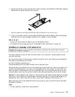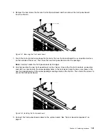
6. Remove the two screws that secure the front panel board and then remove the front panel board
from the chassis.
Figure 131. Removing the front panel board
7. Touch the static-protective package that contains the new front panel board to any unpainted surface
on the outside of the server. Then, take the new front panel board out of the package.
Note:
Carefully handle the front panel board by its edges.
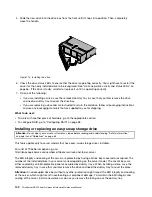
8. Carefully position the new front panel board on the chassis. Ensure that the front controls, connectors,
and LEDs are inserted into the corresponding holes in the front bezel. Align the two screw holes in the
new front panel board with the corresponding mounting studs on the chassis. Then, install the screws to
secure the front panel board.
Figure 132. Installing the front panel board
9. Connect the front-panel-board cables to the system board. See “System board components” on
151
Summary of Contents for ThinkServer RD450
Page 14: ...xii ThinkServer RD450 User Guide and Hardware Maintenance Manual ...
Page 18: ...4 ThinkServer RD450 User Guide and Hardware Maintenance Manual ...
Page 20: ...6 ThinkServer RD450 User Guide and Hardware Maintenance Manual ...
Page 62: ...48 ThinkServer RD450 User Guide and Hardware Maintenance Manual ...
Page 76: ...62 ThinkServer RD450 User Guide and Hardware Maintenance Manual ...
Page 196: ...182 ThinkServer RD450 User Guide and Hardware Maintenance Manual ...
Page 206: ...192 ThinkServer RD450 User Guide and Hardware Maintenance Manual ...
Page 218: ...204 ThinkServer RD450 User Guide and Hardware Maintenance Manual ...
Page 224: ...210 ThinkServer RD450 User Guide and Hardware Maintenance Manual ...
Page 225: ......
Page 226: ......

